
A variable power supply is very useful in electronics lab, as it helps to test many circuits and also it allows changing voltage easily.
This project presents a 0V to 12V adjustable power supply that uses the LM350 adjustable voltage regulator IC, and this IC supplies up to 3A of output current.
First, the rectifier converts the AC voltage from the transformer into DC and next, the filter capacitors smooth the DC voltage, and finally, the LM350 regulator controls the output voltage, also the output voltage adjusted, using a variable resistor potentiometer and therefore, the circuit gives a smooth adjustable voltage.
Therefore, this LM350 Based 0-12V 3A Variable Power Supply Circuit is simple and its components are easy to find, because of this it is good for beginners and hobby electronics projects.
Circuit Working:
Parts List:
| Components | Values | Quantity |
|---|---|---|
| Resistors | 270Ω, 2.2k, 680Ω, 27Ω | 1 each |
| Potentiometer 5k | 1 | |
| Capacitors | Electrolytic 2200µF 35V | 3 |
| Electrolytic 22µF 25V, 47µF 25V, 470µF 25V | 1 each | |
| Ceramic 0.01µF | 1 | |
| Semiconductors | Voltage Regulator IC LM350 | 1 |
| Diodes 1N4007 | 4 | |
| LED standard any color 5mm | 1 | |
| Bridge Rectifier Diodes 6A 100V | 4 | |
| Transformer Center Tap Secondary 12V-0V-12V, Primary 110/220V AC | 1 | |
| Large heatsink for IC LM350 | 1 |
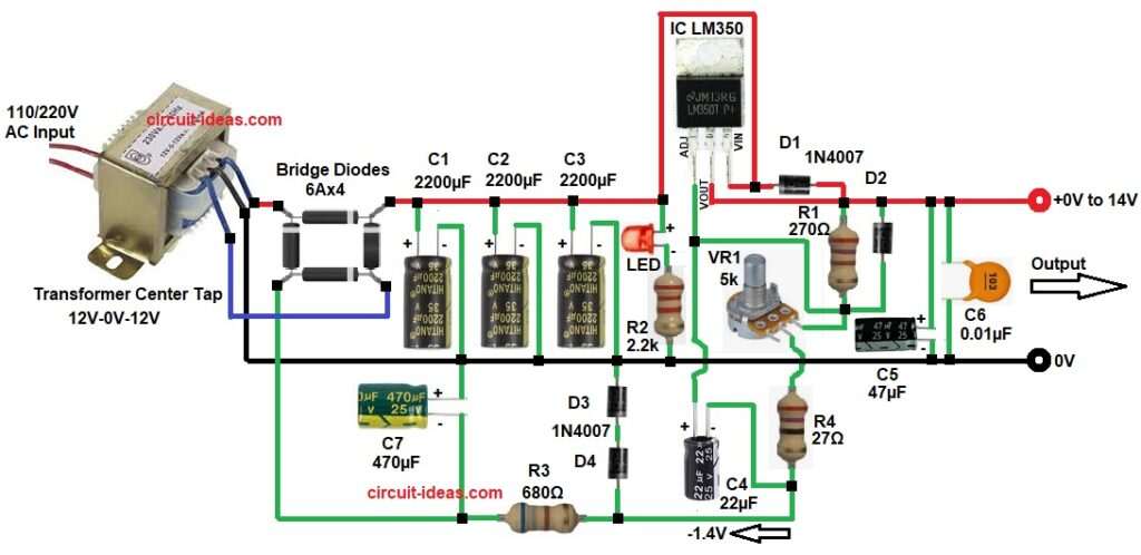
The circuit starts with AC voltage applied to the transformer and this transformer reduces the 220V/110V AC to 12V AC.
Next, the AC voltage goes to the bridge rectifier and the bridge rectifier converts AC into pulsating DC voltage; after that, capacitors C1, C2 and C3 filter the pulsating DC and these capacitors remove ripple and make the DC smoother.
Then the filtered DC voltage enters the LM350 regulator IC and then LM350 regulates the output voltage using resistors R1, R4, and variable resistor VR1. Adjusting VR1 changes the output voltage.
Diodes D1 and D2 protect the regulator from reverse voltage and capacitors C4, C5 and C6 improve stability and reduce noise; also LED1 indicates that the power supply is ON.
Finally, the circuit produces 0V to about 12V adjustable output with current up to 3A.
How the −1.4V Negative Voltage Generated:
In this power supply the circuit creates a small negative voltage of about −1.4V using diodes D3, D4, resistor R3 and capacitor C7.
The transformer center tap acts as the 0V ground and during the negative AC half cycle, diodes D3 and D4 conduct and charge capacitor C7 and this action produces a small negative DC voltage.
Formula for diode drop calculation:
Vnegative = −(Vd1 + Vd2)
where,
- Vd is the diode forward voltage of 0.7V
So, Vnegative = −(0.7 + 0.7) = −1.4V
How to Build:
To build a LM350 Based 0-12V 3A Variable Power Supply Circuit following are the steps we need to follow while doing connection:
- First, gather all the parts as shown in circuit diagram above.
- Then start with transformer secondary to bridge rectifier AC inputs and connect bridge rectifier positive output to filter capacitors positive C1, C2 and C3 and negative to GND line.
- After that, connect filtered DC to pin input of LM350 and connect pin output to resistor R1 270 and connect other side of R1 connect to junction of pin Adjust, diode D2 anode, VR1 one end.
- Further, connect variable resistor VR1 between adjust pin and -1.4V negative supply line through resistor R4 network.
- Connect capacitor C4 between adjust pin and negative bias supply line(-1.4V)
- Connect output capacitor C5 and C6 between output and ground.
- Connect protection diodes D1 and D2 as shown in the circuit.
- Connect LED with resistor R2 in series to indicate power from input pin of IC to GND line.
- Connect capacitor C7 in series with capacitor C1 from GND line to negative bias supply line(-1.4V).
- Lastly, connect diodes D3 and D4 in series with capacitor C3 from GND line to negative bias supply line(-1.4V).
Important note:
- LM350 must use a large heatsink because it can deliver high current.
Conclusion:
Overall, this LM350 Based 0-12V 3A Variable Power Supply Circuit is very useful for electronics testing because it gives stable and adjustable output voltage.
First, the circuit uses an LM350 adjustable voltage regulator which can handle high current and also, the protection diodes and filter capacitors help to improve the reliability and stability of the circuit.
Moreover, the circuit design is simple, so it is easy to build and assemble and therefore this power supply is good for hobbyists, students and small electronics labs.
Finally, with a proper heatsink and a good transformer, the circuit can provide a reliable adjustable DC power source for many electronics projects.