Today security is big problem everywhere.
Many time thief try to open bag or suitcase in bus, train or station.
We cannot always watch our luggage.
This small Luggage Safety Alarm Circuit using IC LM358 help to protect our bag.
It uses piezo sensor and LM358 to sense vibration.
When someone touches or try to open out bag then buzzer rings loud.
This circuit is simple, cheap and can be hidden inside suitcase.
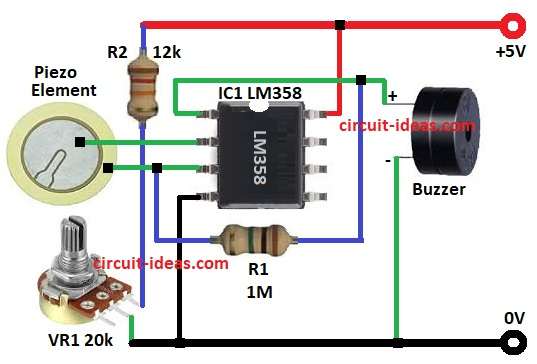
Circuit Working:
Parts List:
| Component | Value | Quantity |
|---|---|---|
| Resistors | ||
| 12k,1M 1/4 watt | 1 each | |
| Potentiometer 20k | 1 | |
| Semiconductors | IC LM358 | 1 |
| Sensor Piezoelectric Disc | 1 | |
| 5V Buzzer | 1 |
This circuit main part is piezo sensor.
Sensor make small voltage when it feel vibration or shock.
Output voltage is weak so we use LM358 IC.
LM358 work here as comparator.
Comparator check sensor voltage with reference voltage.
If sensor voltage is more than reference then output go high and buzzer gets ON.
Resistor R2 give bias to sensor.
VR1 potentiometer is for setting sensitivity.
If VR1 is set high then even small vibration can trigger alarm.
R1 work as pull down and make comparator stable.
When bag is still then there is no vibration, output is low and buzzer goes OFF.
When suitcase is touched or lifted then sensor feels the vibration, comparator output goes high and buzzer sound an alarm
Formula:
Comparator output is HIGH when V+ is more than V-.
V+ is piezo sensor voltage plus bias from R2.
V- is reference voltage from VR1.
So condition is:
Vpz + Vbias > Vref.
- Vpz is sensor voltage from 0.1V to 2V based on vibration.
- Vbias is small voltage across resistor R2 of 12k.
- Vref is voltage set by VR1 from 0V to 5V.
By moving VR1 we can set threshold.
Example: If Vref is 1V then sensor plus bias must be more than 1V.
Then comparator output goes high and buzzer sound.
How to Build:
To build a Luggage Safety Alarm Circuit using IC LM358 follow the below steps for connections:
- First collect all parts as in circuit diagram.
- Pin 1 of LM358 connect to buzzer through resistor R1.
- Pin 2 of LM358 (inverting -) connect to one side of piezo sensor.
- Pin 3 of LM358 (non inverting +) connect to other side of piezo sensor.
- Pin 4 of LM358 is ground, connect to 0V.
- Pin 8 of LM358 is Vcc connects to +5V supply.
Note:
- Piezo sensor is mounted on suitcase body where vibration is easily detected.
- VR1 is fixed on small PCB so user can adjust.
- Buzzer is connected to output and placed hidden in bag.
- Whole circuit powered by 5V small battery pack.
Conclusion:
This is easy and useful mini project.
Luggage Safety Alarm Circuit using IC LM358 protect from thief.
Circuit is small, low cost and uses less power.
VR1 adjust sensitivity of sensor.
We can add relay for big siren or GSM module for SMS alert.
Best part is circuit need few components and fit on small PCB for portable use.
Leave a Reply