Mains AC Power Supply Failure Buzzer(Alarm) Circuit is small device; it makes sound (buzzer) when AC power goes OFF.
Furthermore, it helps us to know power gone and is useful if we have important machine to know power goes at night; also it uses one switch called relay.
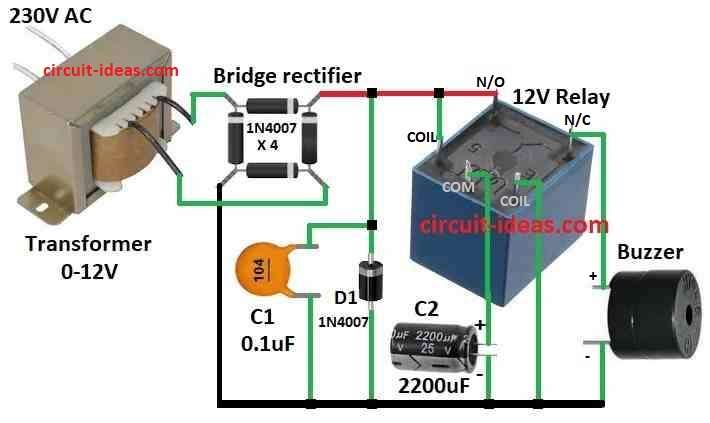
When power is on, the relay operates to stop the buzzer and when power goes out, the relay de-energizes, its contacts switch and the buzzer sounds.
Circuit Working:
Parts List:
| Components | Values | Quantity |
|---|---|---|
| Capacitors | Ceramic 0.1μF | 1 |
| Electrolytic 2200μF 25V | 1 | |
| Semiconductors | Diode 1N4007 | 1 |
| Bridge Rectifier 1N4007 | 4 | |
| 12V Relay | 1 | |
| Buzzer | 1 | |
| 12-0-12V Transformer | 1 |
After making circuit same like diagram plug in to turn ON and then turn OFF the power and wait the buzzer will beep and this way we test the circuit.
Moreover, this work like an emergency light, buzzer sounds when power goes.
At first, transformer change high 220V AC to low 12V AC when power is ON and then bridge rectifier changes 12V AC to DC.
Here, bridge rectifier has 4 special diodes and it makes current go one way in each half of AC; output is DC but direction is the same, also, good thing is no need of a special transformer.
After producing the DC, the current flows through capacitor C2 to remove noise, so we call it a smoothing capacitor.
Another capacitor C1 start charging and then relay turns ON and when power goes OFF the relay goes back and the circuit connects buzzer to capacitor.; hence, buzzer uses power from capacitor and beep until capacitor is empty.
If capacitor is bigger then buzzer beeps longer, also in this setup the buzzer uses 0.310 Amps and if using DC power supply then no need of transformer and rectifier.
Formulas:
Transformer Turns Ratio and this formula help find output voltage of transformer using coil turns and input voltage:
Vo / Vi = Ns / Np
where:
- Vo is the output voltage for 12V AC
- Vi is the input voltage for 220V AC
- Ns turns in secondary coil
- Np turns in primary coil
Use this if we want to know how transformer changes the voltage or if we use different transformer.
Capacitor Charging Time:
We can find how long capacitor C1 takes to charge when power is ON, then we use this formula:
t = CV / I
where:
- t is the time in seconds
- C is the capacitance of C1 in farads
- V is the voltage for 12V DC
- I is the charging current which depends on circuit resistance
Use this if we want to know how long capacitor takes to full charge.
How to Build:
To build a Mains AC Power Supply Failure Buzzer Circuit follow the below mentioned steps for circuit connections:
- First, put all parts same like shown in diagram.
- Next, connect relay common pin to ground using capacitor C2.
- After that, connect relay coil between positive and negative power lines.
- Then connect buzzer to NC (normally closed) pin of relay and to ground.
- Now connect capacitor C1 from positive line to ground and then connect diode D1 between positive line and ground.
- Also, connect positive pin of bridge rectifier to positive line of circuit and connect negative pin of bridge rectifier to negative line.
- Finally, connect 12V AC wires from transformer to AC input pins of bridge rectifier.
Safety Tips:
- Work only if we know how to handle electricity safely, as mains AC is dangerous and it can kill or hurt badly.
- Always turn OFF and disconnect power before touching the circuit and use parts with correct voltage ratings.
- If not sure about electronics then buy ready made power fail buzzer from electronics shop.
Conclusion:
The Mains AC Power Supply Failure Buzzer (Alarm) Circuit indicates when the power goes out, as it turns ON when the main power cuts off, similar to an emergency light.
Also, circuit is simple where relay controls the buzzer, transformer reduces the voltage, bridge rectifier changes AC to DC and capacitors stores and filters power.
Leave a Reply