Metal detector uses electric field to find metal near it.
Making Metal Detector Circuit using Arduino is fun for electronics lovers.
We can make it using Arduino, CS209A chip, LEDs, buzzer and some other parts.
LED and buzzer will show when metal is close.
This project use CS209A chip with Arduino.
CS209A is good chip for finding metal and nearby things.
Coding:
// Declare Arduino Pins
const int vinHi = 2;
const int vinLo = 3;
const int ledG = 4;
const int ledR = 5;
const int Buz = 6;

// Variable to detect state change
int metalState = 0;

// Declare Arduino Pin Mode
void setup() {
  pinMode(vinHi, INPUT);
  pinMode(vinLo, INPUT);
  pinMode(ledG, OUTPUT);
  pinMode(ledR, OUTPUT);
  pinMode(Buz, OUTPUT);
}

void loop() {
  metalState = digitalRead(vinHi); // Read the proximity detector signal

  if (metalState == HIGH) { // No Metal detected
    digitalWrite(ledG, HIGH);
    digitalWrite(ledR, LOW);
    digitalWrite(Buz, LOW);
  } else { // Metal detected
    digitalWrite(ledG, LOW);
    digitalWrite(ledR, HIGH);
    digitalWrite(Buz, HIGH);
  }

  delay(3000); // Wait for 3 Sec.
}
Code Explanation:
- Variables vinHi, vinLo, ledG, ledR and Buz are numbers for Arduino pins.
- Pins 2 and 3 goes to vinHi and vinLo and these read signals.
- Pins 4, 5 and 6 go to ledG, ledR, and Buz and these control green LED, red LED and buzzer.
- metalState is a variable and it stores signal from vinHi pin and it tells if metal is found or not.
- When Arduino turns ON or resets, setup() runs one time.
- pinMode() sets how each pin works.
- vinHi and vinLo are for input so it is set to INPUT
- ledG, ledR and Buz are for output and so it is set to OUTPUT
- After setup(), loop() keeps running again and again.
- In loop(), digitalRead(vinHi) checks metal signal and saves it to metalState.
- If metalState is HIGH then there is no metal.
- With Green LED will be ON and red LED will be OFF and buzzer will be OFF.
- If metalState is LOW then metal is found.
- With Green LED will be OFF and red LED will be ON and buzzer will be ON.
- delay(3000) stops for 3 seconds before checking again.
Circuit Working:
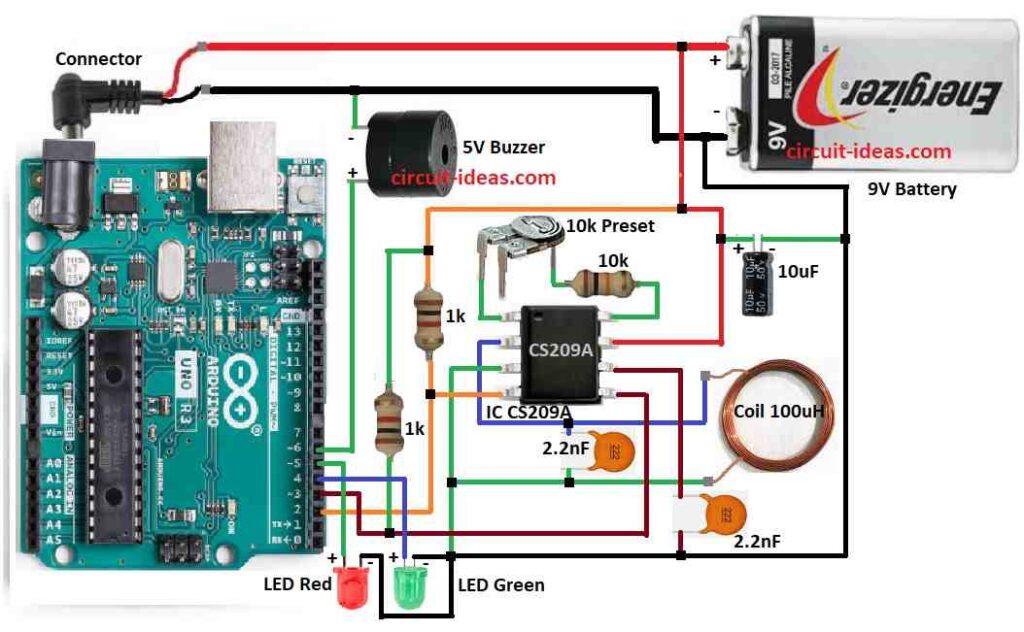
Parts List:
| Component | Specification | Quantity |
|---|---|---|
| Resistors | ||
| 10k 1/4 watt | 1 | |
| 1k 1/4 watt | 2 | |
| Preset 10k | 1 | |
| Capacitors | ||
| Electrolytic 10µF 25V | 1 | |
| Ceramic 2.2nF | 2 | |
| Semiconductors | ||
| Arduino UNO | 1 | |
| IC CS209A Metal Detection | 1 | |
| 5V Buzzer | 1 | |
| LED Red 5mm 20mA | 1 | |
| LED Green 5mm 20mA | 1 | |
| Coil Detector 100µH, 40mm diameter, 50 turns by 0.4 mm insulated copper wire | 1 | |
| 9V Battery | 1 |
Arduino metal detector runs on 9V battery.
Arduino makes square wave signal to power the coil.
Coil makes electromagnetic field and it changes when metal is close.
Coil is 100μH and is made from 0.4 mm copper wire with 50 turns and 40 mm wide.
When metal comes coils inductance changes.
This changes the square wave signal.
Capacitors remove noise and make signal clean.
Resistors control current so parts do not break.
Sensitivity can change using presets.
We can adjust signal strength or detection level.
Op-amp makes signal stronger and cleaner.
CS209A chip sets voltage level to check signal.
If no metal then green LED is ON.
If metal is close by then red LED is ON and buzzer makes sound.
How to Build:
To build a Metal Detector Circuit using Arduino follow the below mentioned steps:
- Collect all parts shown in circuit diagram.
- Connect pin 1 of CS209A to pin 8 using a preset and 10k resistor.
- Connect pin 2 of CS209A to one side of 100μH coil.
- Connect pin 3 of CS209A to other side of coil and to GND.
- Connect pin 4 of CS209A to Arduino pin 2.
- Connect pin 5 of CS209A to Arduino pin 3.
- Connect pin 6 of CS209A to GND using a 2.2nF capacitor.
- Connect pin 7 of CS209A to positive terminal of 9V battery.
- Connect 9V battery negative to GND and place a 10μF capacitor between pin 7 and GND.
- One leg goes to Arduino pin 6.
- Other leg goes to GND.
- Add 1k pull-up resistor between Arduino pin 3 and positive line.
- Add 1k pull-up resistor between Arduino pin 2 and positive line.
- Connect anode long leg to Arduino pin 5
- Connect cathode short leg to GND.
- Anode goes to Arduino pin 4
- Cathode goes to GND.
- Place 2.2nF capacitor between CS209A pin 2 and pin 3.
Conclusion:
This Metal Detector Circuit using Arduino is easy and accurate project.
It uses coil, CS209A chip and Arduino to find metal.
Green light shows no metal and red light and buzzer show metal found.
This circuit is good for learning electronics and sensor projects.