POV means Persistence of Vision.
Our eyes cannot see very fast blinking light separately.
If light blinks very fast then we see it like a line or picture.
Using this idea we can create letters or shapes with some LEDs.
Arduino controls LEDs in speed to make effect of display.
This project uses Arduino Nano, some LEDs, resistors and 9V battery.
LEDs are arranged in line and rotate or move fast.
When Arduino switch ON and OFF LEDs in sequence then it looks like text or design is floating in air.
Circuit coding:
// Arduino POV Display with 10 LEDs and Hall Sensor
// LEDs connected to D2–D9, D11, D12
// Hall sensor connected to D10

const int ledPins[10] = {2, 3, 4, 5, 6, 7, 8, 9, 11, 12}; // 10 LED pins
const int hallPin = 10;                                    // Hall sensor pin
int hallState = 0;

// Example pattern for letter "A" (10 rows)
byte patternA[10] = {
  B0001111000,
  B0010000100,
  B0100000010,
  B0100000010,
  B0111111110,
  B0100000010,
  B0100000010,
  B0100000010,
  B0100000010,
  B0100000010
};

void setup() {
  // Set all LED pins as OUTPUT
  for (int i = 0; i < 10; i++) {
    pinMode(ledPins[i], OUTPUT);
  }
  pinMode(hallPin, INPUT);
}

void loop() {
  // Wait for hall sensor trigger (magnet passes sensor)
  hallState = digitalRead(hallPin);
  if (hallState == LOW) {
    showLetter(patternA); // show letter A
  }
}

// Function to display a letter pattern
void showLetter(byte letter[10]) {
  for (int col = 0; col < 10; col++) {
    for (int row = 0; row < 10; row++) {
      if (bitRead(letter[col], row)) {
        digitalWrite(ledPins[row], HIGH);
      } else {
        digitalWrite(ledPins[row], LOW);
      }
    }
    delayMicroseconds(1000); // adjust for clarity of letter
  }
}
Coding Explanation:
- const int ledPins[10] = {2, 3, 4, 5, 6, 7, 8, 9, 11, 12}
- This array saves pin numbers for all 10 LEDs and each LED connected with a resistor.
- const int hallPin = 10
- Hall sensor output connected to pin D10 of Arduino and is used for rotation synchronization.
- byte patternA[10] = { … }
- This makes a 10×10 binary pattern for letter “A”.
- Each value is one vertical column of the letter.
- 1 = LED ON, 0 = LED OFF.
- void setup()
- Runs one time when Arduino starts.
- All LED pins are set as OUTPUT.
- Hall sensor pin is set as INPUT.
- void loop()
- Runs again and again.
- Arduino keeps checking hall sensor.
- When hall sensor detects magnet with LOW signal and Arduino starts showing the letter by calling showLetter(patternA).
- void showLetter(byte letter[10])
- Function to display a letter column by column.
- Outer loop goes through each column of the letter.
- Inner loop goes through each LED (row).
- If bit = 1 then LED is ON or else LED is OFF.
- After one column is shown then delayMicroseconds(1000) gives short delay before next column.
- How letters appear
- LEDs turn ON/OFF very fast while the strip rotates.
- Our eyes merge the blinking into full shapes.
- Because of persistence of vision we can see floating letters like “A” in the air.
Circuit Working:
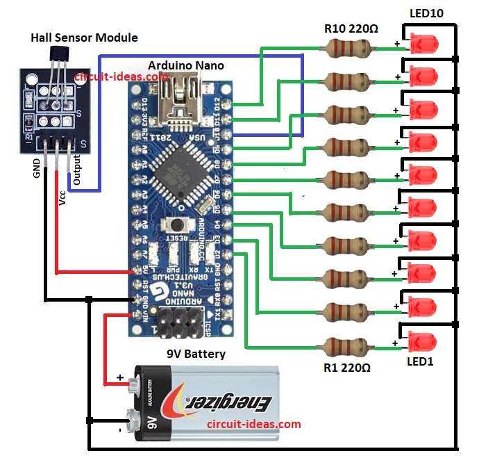
Parts List:
| Component | Specification | Quantity |
|---|---|---|
| Resistors | 220Ω 1/4 watt | 10 |
| Semiconductors | Arduino Nano | 1 |
| Hall Sensor Module | 1 | |
| Red LEDs 5mm 20mA | 10 | |
| 9V Battery | 1 |
The heart of this project is Arduino Nano.
It controls 10 LEDs through pins D2 to D12.
Each LED has resistor in series to limit current.
Arduino take power from 9V battery through Vin pin.
There is also a small IR sensor module in the circuit which is connected to D10 of Arduino.
This sensor is used for synchronizing display or detecting position while rotating.
Sensor sends signal to Arduino at one position and then Arduino start sending pattern to LEDs.
When motor or hand rotates LED strips fast and Arduino blink LEDs in programmed pattern.
Our eye see full letters or symbols because of persistence of vision.
Note:
We can use an old fan which is one of the easiest ways to rotate the LEDs for a POV display.
Many hobbyists do this because:
The fan motor already gives a steady rotation.
It is low cost and easy to find in old table fans, CPU fans or cooler fans.
We can just attach the LED strip with Arduino Nano on one blade or on a piece mounted to the fan.
Formula:
For LED resistor value we use ohms law formula:
R = (Vcc – Vf) / If
here,
- Vcc is 5V from Arduino pin
- Vf is forward voltage of LED which is approx 2V
- If is forward current which is approx 20mA
How to Build:
To build a POV Project with LEDs and Arduino Circuit follow the below steps for connections:
- Take all the parts as shown in circuit diagram
- Arduino Nano Vin pin connected to 9V battery positive
- Arduino Nano GND connected to battery negative
- Pins D2 to D12 are connected to resistors one end and other end are connected to LED anodes in series
- All LED cathodes connected together to ground
- IR sensor module VCC pin connect to 5V pin of Arduino
- IR sensor GND pin connect to Arduino GND
- IR sensor output pin connect to pin D10 of Arduino as per circuit diagram
Conclusion:
This POV Project with LEDs and Arduino Circuit shows how simple parts can create visual magic.
By fast blinking LEDs, Arduino creates words or shapes in air.
This is called Persistence of Vision display.
We can program different patterns or letters.
It is fun project for beginners and also useful for learning timing, sensor and LED control with Arduino.
Leave a Reply