Modern cars must have reverse parking sensors.
These give sound and light signals to help driver avoid crash when going back.
Sensors use infrared or ultrasonic to find objects behind car.
This article for Reverse Car Parking Sensor Circuit using IC LM358 op-amp is to make simple reverse parking sensor circuit.
Circuit is easy and uses basic parts like resistors, presets, LEDs, buzzer and IR pair to find obstacle and alert the driver.
Circuit Working:
Parts List:
| Component | Specification | Quantity |
|---|---|---|
| Resistors (All resistors are 1/4 watt unless specified) | 10k | 1 |
| 150Ω | 1 | |
| 1k | 3 | |
| Presets 10k | 3 | |
| Semiconductors | ||
| IC LM358 | 2 | |
| LED Red 5mm 20mA | 1 | |
| LED Yellow 5mm 20mA | 1 | |
| LED Green 5mm 20mA | 1 | |
| Buzzer | 1 | |
| IR Pair | 1 | |
| Battery 9 Volt | 1 |
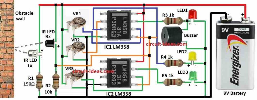
This parking circuit uses two LM358 ICs to compare voltages.
One IR pair is used to find obstacle.
IR receiver connect to all non-inverting pins of comparators.
Each inverting pin has 10k preset to set reference voltage.
Comparators work in non-inverting mode.
Three LEDs show how near the obstacle is.
Red LED and buzzer connect to IC1 output through 1k resistor
Yellow LED also connect to IC1
Green LED connect to IC2
Whole system is fixed at back of a car and sensor faces obstacle like wall.
When car moves back with more than 15 cm from wall then no LED turns ON.
At 15 cm the green LED turns ON.
At 10 cm the yellow LED turns ON.
And at 5 cm the red LED and buzzer turns ON.
Red light and buzzer mean car must stop now or it may hit the wall.
Formulas:
To make and set reverse car parking sensor circuit we need some formulas.
These formulas help understand how IR sensor and LM358 op-amp work.
1. IR LED Current use ohms law:
ILED = Vcc − VLED / RLED
where,
- Vcc is the 9V supply
- VLED is the IR LED forward voltage from 1.2V to 1.5V
- RLED is the resistor with IR LED for 1k
- ILED is the current in IR LED
2. Comparator Threshold Voltage (Vref):
Vref = Rpreset/ Rpreset+ Rfixed × Vcc
where,
- Rpreset is the preset for 10k
- Rfixed is the fixed resistor in voltage divider
- Vcc is the 9V supply
This helps to set when output turns ON.
3. LED Current when op-amp output is high:
ILED = Vcc − VLED / RLED
where,
- VLED is the LED forward voltage to about 2V for normal LED
- RLED is the resistor with LED with 1k
With these formulas we can build and set our car parking sensor easily and correctly.
How to Build:
To build a Reverse Car Parking Sensor Circuit Using IC LM358 below mentioned are the steps to follow:
- Connect pin 2 of IC1 to front leg of VR2 preset.
- Connect pin 3 of IC1 to R4 resistor, Yellow LED2 and then to ground.
- Connect pin 4 of IC1 to 3rd leg of VR1 preset as shown in circuit diagram.
- Connect pin 5 of IC1 to pin 5 of IC2.
- Connect pin 6 of IC1 to front leg of VR1 preset.
- Connect pin 7 of IC1 to R3 resistor, Red LED1 and then to ground.
- Connect pin 8 of IC1 to positive supply.
- Connect pin 4 of IC2 to ground.
- Connect pin 5 of IC2 to pin 5 of IC1.
- Connect pin 6 of IC2 to front leg of VR3 preset.
- Connect pin 7 of IC2 to R5 resistor, Green LED3 and then to ground.
- Connect pin 8 of IC2 to positive supply.
- Connect 2nd leg of VR1, VR2, VR3 to positive and 3rd leg to ground.
- Connect IR Rx and R2 from positive to ground.
- Connect IR Tx and R1 from positive to ground.
- Connect buzzer between R3 and LED1 and other leg to ground.
- Connect 9V battery positive to circuit positive and negative to ground.
Conclusion:
This Reverse Car Parking Sensor Circuit using IC LM358 is simple and useful project.
It helps car not hit anything when going back.
It uses IR sensor, op-amp, LEDs and buzzer to give sound and light alerts.
Building this circuit helps us learn how sensors and op-amps work together in electronics.
Leave a Reply