Transistors are very important in electronics.
They make signals strong and turn things ON/OFF and do many jobs.
To check if its good then we need to test them.
Testing helps find problems and broken parts.
This article for Simple 555 Timer Based Transistor Tester Circuit show easy way to test transistors with 555 timer IC.
Tester works for NPN and PNP transistors.
If transistor is good then LED will light.
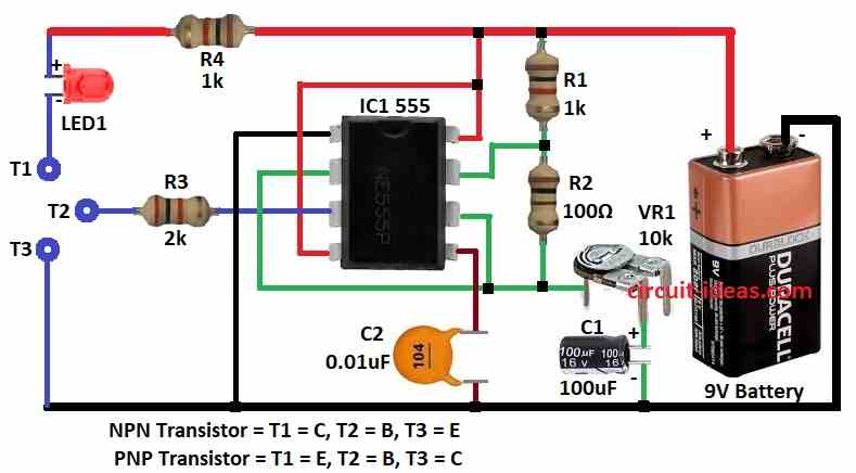
Circuit Working:
Parts List:
| Component | Specification | Quantity |
|---|---|---|
| Resistors | 1k 1/4 watt | 2 |
| 100Ω 1/4 watt | 1 | |
| 2k 1/4 watt | 1 | |
| Preset 10k | 1 | |
| Capacitors | Ceramic 0.01μF | 1 |
| Electrolytic 100μF 16V | 1 | |
| Semiconductors | IC 555 | 1 |
| LED any 5mm 20 mA | 1 | |
| Battery 9V | 1 |
In this article, 555 timer works as astable multivibrator.
It makes square wave signal.
This signal goes to base of transistor we test.
Square wave turns transistor ON and OFF again and again.
For NPN transistor connect collector to T1, base to T2 and emitter to T3.
For PNP transistor connect emitter to T1, base to T2 and collector to T3.
If LED blinks then transistor is working good.
Blinking means transistor switching ON/OFF with square wave.
If LED stays OFF then transistor maybe bad or with wrong connection.
Formulas with Calculations:
555 Timer Transistor Tester Formulas with Example:
1. Frequency of 555 Timer (Astable Mode):
Formula:
f = 1.44 / ((R1 + 2 * R2) * C1)
where:
- R1 is 1kΩ
- R2 is 10kΩ from VR1
- C1 is 100μF
Calculation:
f = 1.44 / ((1000 + 2*10000) * 0.0001)
f = 0.686 Hz
So timer gives about 0.686 Hz output signal.
2. LED Resistor R4:
Formula:
R4 = (Vcc – V_LED) / I_LED
where:
- Vcc is 9V
- V_LED is 2V
- I_LED is 20mA
R4 = (9 – 2) / 0.02 = 350Ω
But use 1kΩ for more safety to LED.
3. Charge and Discharge Time of Capacitor:
Charge time (High):
t_charge = 0.693 * (R1 + R2) * C1
t_charge = 0.693 * (1000 + 10000) * 0.0001 = 0.763 sec
Discharge time (Low):
t_discharge = 0.693 * R2 * C1
t_discharge = 0.693 * 10000 * 0.0001 = 0.693 sec
So LED turns ON and OFF every 0.7 sec.
This shows how long LED stays ON or OFF.
How to Build:
To build a Simple 555 Timer Based Transistor Tester Circuit follow the below mentioned steps for connections:
- Connect pin 1 of IC1 555 to GND.
- Connect one side of VR1 to point between R1 and pin 2 of IC1.
- Other side of VR1 goes to positive of C1 and negative of C1 to GND.
- Pin 3 of IC1 goes to T2 base of transistor to test NPN or PNP.
- Connect pin 4 and pin 8 of IC1 to +9V supply.
- Pin 5 goes to GND using capacitor C2.
- Pin 6 connects to pin 2 of IC1.
- Pin 7 connects between R1 and R2 in series.
- T1 collector goes to +9V through LED1 and resistor R4.
- T3 emitter connects to -9V GND of battery.
Conclusion:
This Simple 555 Timer Based Transistor Tester Circuit is easy and useful.
It tests both NPN and PNP transistors.
555 gives square wave to check if transistor works.
Few parts, simple setup is good for beginners and for a handy testing tool
Leave a Reply