• Skip to primary navigation
  • Skip to main content
  • Skip to primary sidebar

Circuit Ideas for You

Get free circuit ideas online.

  • Home
  • Privacy Policy
  • About
Home » Simple 9V Battery Powered Transistor Intercom Circuit

Simple 9V Battery Powered Transistor Intercom Circuit

Last updated on 14 February 2025 by Admin-Lavi Leave a Comment

An intercom system is a device that lets people talk to each other over short distances.

The Simple 9V Battery Powered Transistor Intercom Circuit is great for helping people communicate in places like homes or offices.

This circuit is easy to understand and works really well using only transistors to make it function.

It runs on a 9V battery and has a microphone and a small speaker to create sound.

The circuit uses BC547 transistors to make the sound louder and a 2N2222 transistor is used to power the speaker properly.

Circuit Working:

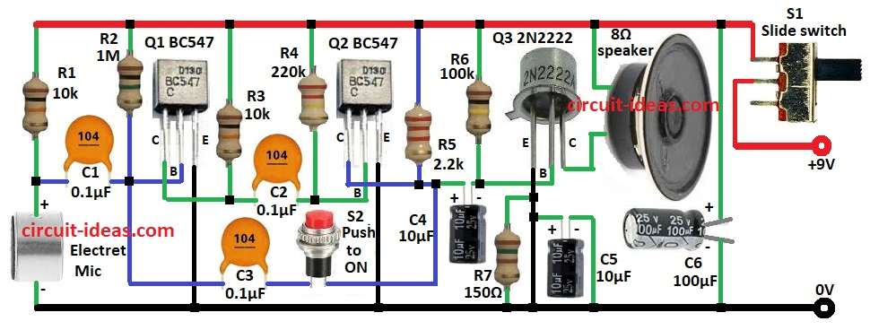
Simple 9V Battery Powered Transistor Intercom Circuit Diagram

Parts List:

ComponentValue/TypeQuantityNotes
Resistors (1/4W unless specified)
Resistor10k2
Resistor1M1
Resistor220k1
Resistor2.2k1
Resistor100k1
Resistor150Ω1
Capacitors
Ceramic Capacitor0.1µF3
Electrolytic Capacitor10µF 25V2
Electrolytic Capacitor100µF 25V1
Semiconductors
TransistorBC5472
Transistor2N22221
Other Components
Electret Microphone–1
Push-to-ON Switch–1
Slide Switch–1

The circuit starts with an electret microphone which is really important for picking up sounds from around it.

These sounds are pretty weak at first so they need to be made stronger before anything else can happen.

To help clean up and stabilize the microphones output resistor R1 works together with capacitor C1.

The first transistor Q1 acts as a preamplifier to boost the signals strength.

Resistor R2 helps with the necessary biasing while R3 helps keep the circuit stable.

    After the signal is amplified it goes through capacitor C2 to the next amplification stage.

    In this part the second transistor Q2 makes the signal even stronger.

    The gain for this stage is set by resistors R4 and R5.

    To make sure the signal travels smoothly capacitor C3 is used.

    The last amplification stage is handled by Q3 a power transistor, which can effectively drive an 8 ohm speaker.

    Resistors R6 and R7 help with proper biasing and current control.

    Capacitors C4 , C5 and C6 are added to filter out noise and ensure everything runs smoothly.

    The whole circuit is powered by a 9V battery and switch S1 is used to turn the intercom system on or off.

    Additionally, S2 acts as a push-to-talk button that activates the circuit when pressed.

    Note:

    To build a two way intercom circuit, you need to create two identical versions of the circuit shown above.

    Then, connect them following the connection diagram provided.

    This circuit uses about 20mA of current when it is on standby.

    Formulas with Calculations:

    Voltage Gain of Each Transistor Stage:

    The voltage gain (Av) of a transistor amplifier stage is given by:

    Av​ = RC​​ / RE​

    For the first transistor stage Q1:

    Collector resistor RC​ = 10k

    Emitter resistor RE = 1k (assumed)

    Av​1 = 10k / 1k ​= 10

    For the second transistor stage Q2:

    Collector resistor RC = 2.2k

    Emitter resistor RE​ = 220k

    Av​2 = 2.2k / 220k =100

    Total voltage gain:

    Atotal​ = Av​1 × Av​2 = 10 × 100 =1000

    Speaker Power Calculation:

    Power delivered to an 8Ω speaker can be estimated using the formula:

    P = V2​ / R

    Assuming the transistor outputs around 6V RMS:

    P = 62 / 8​ = 36 / 8​ = 4.5W

    Thus, the speaker receives approximately 4.5W of power.

    How to Build:

    To build a Simple 9V Battery Powered Transistor Intercom Circuit following steps for connections are needed to be followed:

    • Gather all the components mentioned in the above circuit diagram:
    • Connect resistor R1 and electret Mic in series from positive supply to GND.
    • Connect collector of transistor Q1 to positive supply through resistor R3
    • Connect the base of transistor Q1 to one end of resistor R2 and other end of R2 to positive supply
    • Connect capacitor C1 one end between resistor R1 and MIC and other end to base of transistor Q1
    • Connect emitter of transistor Q1 to GND.
    • Connect transistor Q2 base to positive supply through resistor R4
    • Connect a capacitor C2 one end between collector of Q1 transistor and resistor R3 and other end of C2 to base of transistor Q2.
    • Connect the collector of transistor Q2 to positive supply through resistor R5.
    • Connect the emitter of transistor Q2 to GND
    • Connect the base of transistor Q3 to positive supply through resistor R6.
    • Connect capacitor C4 positive end resistor R5 and negative end of capacitor to resistor R6
    • Connect capacitor C3 and S2 switch in series from the base of transistor Q1 and positive of capacitor C4
    • Connect emitter of transistor Q3 to GND and connect a resistor R7 and capacitor C5 in parallel from emitter of Q3 transistor and GND.
    • Connect collector of transistor Q3 to one end of 8 ohm speaker and other end of speaker connect to positive supply
    • Connect positive of capacitor C6 to positive supply of the circuit and negative of capacitor C6 to GND.
    • Connect one pin of switch S1 from positive supply of circuit and second pin to +9V DC.

    Conclusion:

    This Simple 9V Battery Powered Transistor Intercom Circuit is a great budget friendly option for talking over short distances.

    It has basic parts but still provides clear sound.

    You can also change the design to make it louder or include extra features like a volume knob.

    References:

    simple microphone – speaker circuit

    Filed Under: Audio Circuits, Transistor Circuits

    About Admin-Lavi

    Lavi is a B.Tech electronics engineer with a passion for designing new electronic circuits. Do you have questions regarding the circuit diagrams presented on this blog? Feel free to comment and solve your queries with quick replies

    Previous Post: « Simple Transistor Based Battery Heater Circuit
    Next Post: Tone Generator Doorbell Circuit using Dual IC 555 Timers »

    Reader Interactions

    Leave a Reply Cancel reply

    Your email address will not be published. Required fields are marked *

    Primary Sidebar

    Categories

    • Alarm Circuits (30)
    • Amplifier Circuits (67)
    • Arduino Projects (29)
    • Audio Circuits (93)
    • Automobile Circuits (19)
    • Battery Charger Circuits (48)
    • Free Energy (13)
    • Heater and Temperature Controllers (9)
    • Indicator Circuits (38)
    • Inverter Circuits (13)
    • LDR Circuits (13)
    • LED and Lamps (111)
    • Meters and Testers (27)
    • Motor Controllers (18)
    • Oscillator Circuits (32)
    • Power Supply Circuits (91)
    • Remote Control Circuits (6)
    • Security and Protection (23)
    • Sensors and Detectors (71)
    • Solar Circuits (16)
    • Timer Circuits (27)
    • Transistor Circuits (56)
    • Transmitter Circuit (12)
    • Tutorials (4)
    • Water Level Controller (4)

    Copyright © 2025 | New Circuit Ideas