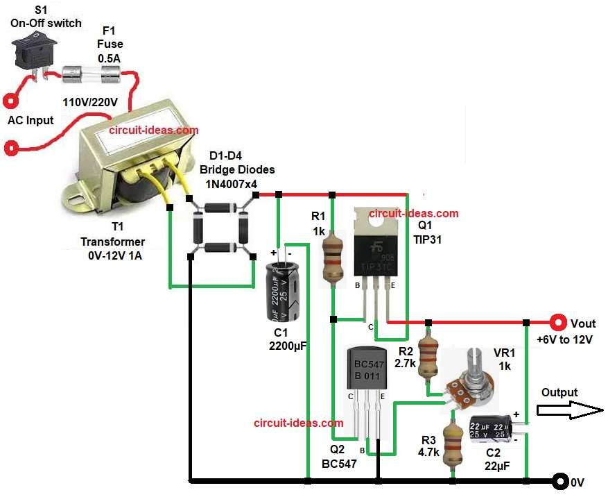
This post is for Simple Adjustable 5V to 12V Voltage Regulator Circuit using TIP31 which uses transformer, bridge rectifier, filter capacitor and transistor control stage.
The circuit can give output voltage from about 5V to 12V DC, as it uses TIP31 power transistor to handle load current.
We can adjust the potentiometer VR1 to set the output to 9V if we require and the maximum current we can get is 1A.
This project is useful for small lab supply, hobby projects and testing circuits.
Circuit Working:
Parts List:
| Components | Values | Quantity |
|---|---|---|
| Resistors (All resistors are 1/4 watt) | 1k, 2.7k, 4.7k | 1 each |
| Potentiometer 1k | 1 | |
| Capacitors | Electrolytic 2200µF 25V, 22µF 25V | 1 |
| Semiconductors | TIP31 Power Transistor | 1 |
| Control Transistor BC547 | 1 | |
| Bridge Rectifier Diodes 1N4007 | 4 | |
| Transformer primary 110V/220V AC, Secondary 0V-12V 1A | 1 | |
| On/Off Switch | 1 | |
| Fuse 0.5A | 1 | |
| Output Voltage Adjustable 6V to 12V DC | – | |
| Heatsink for power transistor TIP31 | 1 |
AC input comes to transformer through switch and fuse and the transformer steps down voltage from 220V AC to 12V AC.
Bridge rectifier D1 to D4 converts AC to DC and output is pulsating DC.
Capacitor C1 filters ripple by making smooth DC and now DC goes to regulator section.
Q1 TIP31 works as series pass transistor as it controls output voltage and Q2 BC547 works as control transistor which senses voltage and adjusts Q1 base current.
R1 gives base current to Q1 and VR1 sets output voltage and when user rotates VR1 then voltage at base of Q2 changes.
Q2 then changes current flow to Q1 base and this action increases or decreases output voltage.
R2, R4 set bias and stability, C2 gives extra filtering at output which reduces noise and ripple.
So circuit converts AC to stable adjustable DC output.
How to Build:
To build a Simple Adjustable 5V to 12V Voltage Regulator Circuit using Transistors following are the steps one needs to follow for connections:
- Start, the circuit by collecting all the parts as in diagram above.
- Then start with transformer T1 primary side connect to AC mains with switch S1 and fuse F1 and secondary gives 12V AC.
- Bridge rectifier D1 to D4 connect four diodes in bridge form.
- AC ends go to transformer secondary and positive and negative give DC output.
- Capacitor C1 positive side go to DC positive line and negative goes to ground.
- After that start with TIP31 transistor Q1 pin base connect to R1.
- Pin collector connect to DC input and pin emitter gives output from 6V to 12V.
- Then start with second BC547 transistor Q2 with pin emitter connect to ground.
- Pin base connect to VR1 middle pin and pin collector connect to Q1 base through resistor network R1.
- Potentiometer VR1 one end goes to output, other end goes to one end of resistor R4 and middle pin to Q2 base.
- Resistors R1 connect between DC positive and Q1 base.
- R2 one end connect between Q1 emitter and Vout and other end connect to VR1 one end.
- R3 one end connect to one end of VR1 and other end connect to GND.
- Lastly, capacitor C2 positive goes to Vout output and negative end of capacitor goes to ground
Conclusion:
This Simple Adjustable 5V to 12V Voltage Regulator Circuit using Transistors gives variable output from 5V to 12V.
Power transistor TIP31 handles higher current, user can adjust voltage using VR1.
Circuit needs heat sink for safe operations and it is good for beginners and small electronics projects.
Leave a Reply