Want to change how bright the LED light is?; then we can use adjustable LED dimmer circuit for that.
Furthermore, this small and Simple Adjustable LED Dimmer Circuit helps to control LED brightness so one get just right light for any time.
Also, by turning some parts like resistor, transistor and one special knob (called potentiometer), this circuit change how much power the LED will requires to make it more bright or more dim as one likes.
Circuit Working:
Parts List:
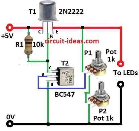
Here, is one easy LED dimmer circuit which uses only 2 transistors, 1 resistor and 2 potentiometers.
Normal LED display use around 25mA for each segment, so we usually need resistors to stop too much current and if we use 6 digit display we need around 42 resistors in series, that is too lot!
But this LED dimmer fixes that problem and it lets control brightness with only few parts; also no need of many resistors so PCB is easier to make and put together.
Moreover, this circuit work like voltage regulator and it gives power that one can change.
The regulator changes the voltage and the LED brightness goes up or down because of this voltage change.
Potentiometer P1 is for big brightness change and P2 is for small fine adjust, hence, this circuit can change voltage from 0 to 4.3 volts.
To use it, first turn both potentiometers to zero and then slowly turn them until light is good for anyone.
In 6 digit display total current must not go more than 1 ampere, for example each segment take 25mA. 6 digits × 7 segments = 1050mA (a little more than 1 amp).
Hence, because of this big current transistor T1 can get hot and so it need good heat sink to keep it cool.
Formulas:
Current Going Through LED:
To know how much current will the LED require one needs to know two things:
- LED working current (ILED)
- LED forward voltage (VLED)
The resistors and transistors in circuit also change how much current goes to LED.
Formula:
ILED = (VCC − VLED) / RLED
where:
- VCC is power supply voltage
- VLED is the forward voltage of the LED
- RLED is total resistance in line with LED (can be from resistor, potentiometer or effect of transistor)
In this circuit, RLED means the load resistance and turning the potentiometer changes it along with the transistor operation.
Potentiometer Resistance and Controlling Current:
The small transistor BC547 get base current from potentiometer and this current then controls big transistor 2N2222; also this setup affects how bright the LED glows.
Base Current of BC547 IB:
IB = VPot−VBE(BC547) / RPot
where,
- VPot is voltage from potentiometer (can move from 0 to 5V)
- VBE (BC547) is about 0.7V (base to emitter voltage)
- RPot is the resistance of potentiometer (like 1k ohm)
All these small calculations help to understand how circuit work; depending on real components and values numbers can change so always test and adjust.
How to Build:
To build a Simple Adjustable LED Dimmer Circuit following are the steps one should follow for connection:
Get All Parts:
- First, collect all needed parts listed in the above circuit diagram.
Prepare Circuit Design:
- Next, plan how to put parts on breadboard or PCB and leave enough space for LED display and the 2 potentiometers.
Connect Transistors:
- After that, put the transistors in place like in the diagram and transistor T1 controls the current going to the LED.
Add Resistor:
- Then add resistor in series with LED display and this resistor helps to stop too much current; also value depends on LED and how much current one want.
Put Potentiometers:
- Now, connect both potentiometers, P1 is for big adjustment and P2 is for small fine tuning of brightness.
Wire LED Display:
- Connect LED segment display to rest of circuit and also be careful with + and − side (polarity).
Heat Sink for T1:
- If the circuit uses too much current, T1 transistor can get hot; then put a heat sink on it to keep it cool.
Power the Circuit:
- Now connect power supply to the circuit.
Test the Circuit:
- Turn ON power and start with potentiometers at low level and than slowly turn them to see LED to get brighter.
Make Adjustments:
- Turn potentiometers more to get just the right brightness.
Stay Safe:
- Be sure voltage and current is not too high as this stops damage or overheating.
Note:
- Always double check the wiring and if one is not sure about anything ask someone who knows electronics or get expert help.
Conclusion:
To conclude, a Simple Adjustable LED Dimmer Circuit gives us more control on LED light also we can change brightness how one wants and so it work good for many different lighting needs.

Leave a Reply