This post show how to make a Simple Arduino LED Dimmer Circuit using PWM, as PWM changes voltage by changing square wave duty cycle; also it changes duty cycle to make LED more or less bright.
Therefore, more power means more brightness.
Arduino Code:
#define LED_PIN 9
#define BUTTON1_PIN 2
#define BUTTON2_PIN 3

int brightness = 0;

void setup() {
  pinMode(LED_PIN, OUTPUT);
  pinMode(BUTTON1_PIN, INPUT_PULLUP);
  pinMode(BUTTON2_PIN, INPUT_PULLUP);
}

void loop() {
  if (digitalRead(BUTTON1_PIN) == LOW)
 {
    brightness++;
    if (brightness > 255) {
      brightness = 255;
    }
  }

  if (digitalRead(BUTTON2_PIN) == LOW) {
    brightness--;
    if (brightness < 0) {
      brightness = 0;
    }
  }

  analogWrite(LED_PIN, brightness);
  delay(10);
}- LED and button pins use constant names like LED_PIN, BUTTON1_PIN, BUTTON2_PIN.
- Variable “brightness” store how bright LED is now.
- setup() make button pins input with pull-up and LED pin output.
- loop() always check button press.
- BUTTON1 increases the brightness, while BUTTON2 decreases it.
- analogWrite() set PWM duty cycle to control LED brightness.
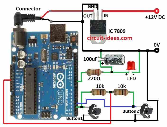
Circuit Working:
Parts List:
| Components | Quantity |
|---|---|
| Resistor | |
| 220Ω 1/4 watt | 1 |
| 10k 1/4 watt | 2 |
| Capacitor | |
| 100µF 25V | 1 |
| Semiconductors | |
| IC 7809 | 1 |
| Arduino Uno board | 1 |
| LED 5mm 20mA any color | 1 |
| Tactile switches | 2 |
LED must connect correct like in circuit diagram, so the push buttons may be unstable, but they will not cause any errors.
Also, using PWM on Arduino is easy and on ATMEGA it is hard because many settings need change; but in Arduino already set these things so we just use right function for PWM and also Arduino makes square wave signal on LED pin.
Furthermore, resistors and capacitor change square wave to DC voltage and duty cycle control average DC voltage which controls LED brightness.
So press button1 the duty cycle goes up and LED goes more bright and then press button2 the duty cycle goes down and LED goes less bright.
How to Build:
To build a Simple Arduino LED Dimmer Circuit using PWM follow the below mentioned steps:
- First, gather all parts as per the circuit diagram.
- Next, connect IC1 7809 to give 9V DC power to Arduino board.
- After that, connect 100μF capacitor positive side between 220Ω resistor and red LED and negative side to GND.
- Then connect 220Ω resistor and red LED in series from pin 9 and LED cathode goes to GND.
- Now connect button1 one leg to pin 2 and other leg to GND and then connect button2 one leg to pin 3 and other leg to GND.
- Also, connect 10k resistor between pin 2 and 5V and then connect another 10k resistor between pin 3 and 5V.
Conclusion:
To conclude, this article for Simple Arduino LED Dimmer Circuit using PWM show how to use PWM with Arduino to control LED brightness in simple and easy way.
Also, by learning PWM and code we can make many light control projects.
Leave a Reply