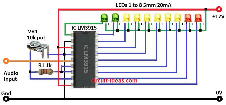
Simple Audio Level Indicator Circuit using IC LM3915 show sound strength with lights.
Its display driver is good for sound visual circuits.
It takes analog voltage and can light up 10 LEDs, LCDs or other displays in line.
Music lovers like it because it show sound level with lights.
IC LM3915 make LED sound meter easy to build.
Circuit Working:

Parts List:
| Category | Component | Quantity |
|---|---|---|
| Resistor | 1k 1/4 watt | 1 |
| Preset 10k | 1 | |
| Semiconductors | IC LM3915 | 1 |
| LED Green 5mm 20mA | 2 | |
| LED Yellow 5mm 20mA | 6 | |
| LED Red 5mm 20mA | 2 |
This above audio level circuit is easy to make.
LM3915 chip show sound level like VU meter.
It split audio into 10 parts and compare with inside reference.
Has 10 outputs and each for one LED.
Voltage divider set level for pins.
Audio signal change to DC and go through resistor network.
If pin voltage is more than reference then that LED turns ON.
Formulas:
When making audio level circuit with LM3915 remember these key formulas:
1. Reference Voltage (Vref):
Set by voltage divider using 10k preset and 1k resistor.
Vref = Vin × (Rpreset / (Rpreset + R1k))
where,
- Vin is the input voltage from audio
- Rpreset is the 10k resistor
- R1k is the 1k resistor
2. LED Current Limiting Resistor RLED:
Use ohms law to find resistor for LED safety:
RLED = (Vsupply − VLED) / ILED
where,
- Vsupply is the power supply for example 12V
- VLED is the LED voltage drop to about 2V for red, green and yellow
- ILED is the LED current which is usually 20mA
3. Segment Reference Voltage (Vi):
Each LED turns ON based on voltage level:
Vi = Vref × i
where,
- Vi is the voltage for i-th LED
- i is the LED number from 0 to 10
Use these formulas to build and tune the audio level circuit with LM3915 properly.
How to Build:
To build a Simple Audio Level Indicator Circuit using IC LM3915 following are the connections steps mentioned below:
- Collect all parts shown in the circuit diagram.
- Connect pin 1 of LM3915 to cathode of 1st green LED.
- Keep going with pin 10 to pin 18 connect to rest LEDs with cathode side.
- Connect LED anodes to +12V power supply.
- Connect pin 2 of LM3915 to ground.
- Connect pin 3 and pin 9 to +12V supply.
- Connect pin 4 to one leg of preset VR1.
- Connect pin 5 to audio input.
- Join pin 6 to pin 7.
- Connect one end of resistor R1 to pin 7 and other end to pin 8.
- Connect pin 8 to middle leg of preset VR1.
Conclusion:
This is easy way to build Simple Audio Level Indicator Circuit using IC LM3915.
It helps see sound level by turning analog audio into blinking LEDs.
Leave a Reply