Nowadays, saving electricity is very important and mostly in city where power is not enough.
This article for Automatic Day Night Switch Circuit show how to make easy auto light switch which turn ON or OFF light when outside light changes and through this way people can save money on electric bill.
What is a Automatic Day Night Switch Circuit:
People call an Automatic Day Night Switch Circuit a light sensor switch or evening light switch because it turns lights ON at night and OFF during the day and this circuit automatically senses darkness to activate lighting and brightness to deactivate it
Also, outside lights, streetlights, and other systems need automatic light control based on outside light, so this circuit mainly works for that purpose.
Circuit Working:
Parts List:
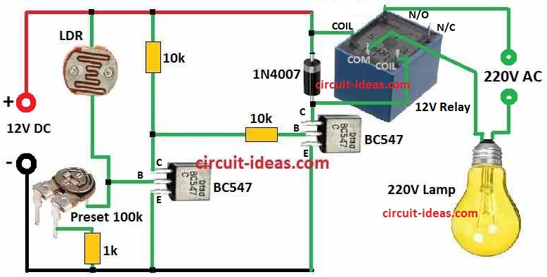
| Components | Values | Quantity |
|---|---|---|
| Resistors (All resistors are 1/4 watt) | 10k | 2 |
| 1k | 1 | |
| LDR | 1 | |
| Preset 100k | 1 | |
| Semiconductors | Transistor BC547 | 2 |
| Diode 1N4007 | 1 | |
| Relay 12V | 1 |
To begin with, this circuit uses two transistors Q1 and Q2 and one LDR.
First, when light come on LDR its resistance goes up and Q1 turn ON so relay also turn ON and when there is no light Q1 turn OFF and relay also goes OFF.
Hence, this way circuit switches things automatic which is good to control lights in day and night.
Also, using this simple day night circuit can help save electricity and also helps solve todays energy problem in small way
Formulas:
Below is formula for Automatic Day Night Switch Circuit:
LDR (Light Sensor) Resistance:
RLDR ∝ 1 / ILDR
where:
- RLDR is the resistance of LDR
- ILDR is the current going through LDR
Transistor Q1 Turn ON Voltage:
VT1 = VBE1 + ILDR × RLDR
where:
- VT1 voltage needed to turn ON Q1
- VBE1 is the base to emitter voltage of Q1
Transistor Q2 Turn ON Voltage:
VT2 = VBE2 + (VCC − ILDR × RLDR)
where:
- VT2 voltage needed to turn ON Q2
- VBE2 is the base to emitter voltage of Q2
- VCC is the supply voltage
Relay Turn ON Time:
τ = RRelay × CRelay
where:
- RRelay is the resistance of relay coil
- CRelay is the capacitor with relay
Note:
Thus, these formula show how resistance, current and voltage work in this circuit and with the help of this simple auto day night switch circuit we can make it easily.
How to Build:
Follow the below mentioned steps for building a Automatic Day Night Switch Circuit:
- First, collect all parts and keep on clean table.
- Next, when picking resistors, capacitors, diodes check they match circuit values.
- Then connect LDR with the circuit.
- Remember Q1 and Q2 change ON/OFF because LDR resistance change when light changes.
- After that, use NPN transistors for Q1 and Q2, in daytime Q1 turn ON and make relay work and at night Q2 turn ON and take control.
- Then check that relay connects to correct transistor and this setup helps turn ON/OFF light or other things in day and night.
- Also, we can use 100k variable resistor to adjust how sensitive circuit is and this help circuit to work better in different places.
- Lastly, use 5V to 12V DC battery but be sure voltage matches with relay specifications.
Conclusion:
Finally, this Automatic Day Night Switch Circuit works by sensing light level, so it turns ON and OFF without manual control.
Therefore, in daytime it switch OFF load and in night it switch ON load automatically, also it save energy and make system more smart.
In addition, it is simple to build and useful for street light, home light and other automatic lighting systems, so overall this circuit give easy and efficient light control.
Leave a Reply