This Simple Beeper Circuit show us how to make a easy beeper circuit.
When we press push button a sound comes from unbalanced multivibrator circuit.
Small speaker makes the sound.
This project is good to learn music and electronics and is also fun project for beginners.
What is a Beeper Circuit:
The beeper circuit is simple but also little advanced.
It keeps beeping again and again so it is good for use like alert or signal in hospital, police station or fire station.
Circuit Working:
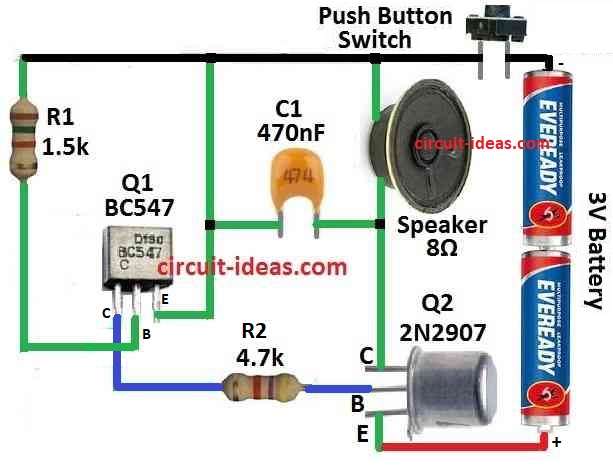
Parts List:
| Category | Description | Quantity |
|---|---|---|
| Resistors | 1.5k CFR 1/4 W | 1 |
| 4.7k CFR 1/4 W | 1 | |
| Capacitor | Ceramic 470nF | 1 |
| Semiconductor | Transistor BC547 | 1 |
| Transistor 2N2907 | 1 | |
| Speaker 8Ω | 1 | |
| Battery 3V | 1 | |
| Push button switch | 1 |
The beeper circuit from above is work like one side multivibrator.
It makes sound we can hear using feedback with two transistor one NPN and other one is PNP.
Pushbutton start the circuit and one resistor help to change the beep sound speed with audio frequency.
Here is how the circuit work step by step:
First we press the pushbutton to start circuit.
Before button press circuit is stable.
One transistor is ON means working other is OFF which means not working.
Example: Q1 transistor NPN is ON and Q2 PNP is OFF.
After press button circuit change fast.
Q1 was ON then goes OFF and Q2 was OFF which turn ON.
Now both transistors try to work together and this make unstable situation.
When Q2 turn ON capacitor near its collector begin to charge.
How fast capacitor charge decide how long this unstable time last.
After capacitor is full enough Q2 turn OFF.
Now circuit goes back to stable Q1 is ON, Q2 is OFF.
Now Q1 is ON so capacitor near it start to discharge and this prepare circuit for next round.
If button is still pressed then this ON/OFF cycle keep happening again and again.
This make pulse sound from speaker or earphone.
We can change beep sound speed by changing resistor R1.
R1 control how fast capacitor charges and discharges.
This circuit also work with earphone like 500 ohm
Sound still comes the same way.
Formulas:
Following are the formulas with calculations for Simple Beeper Circuit:
One can develop a basic astable multivibrator circuit to make a beeper circuit.
When the push button switch is pressed this circuit creates a square wave signal to drive the speaker and release a beeping sound.
How to Find Beep Frequency:
For easy multivibrator circuit we can find how fast it beep using this formula:
f = 1.44 / (R1 + 2 × R2) × C
where:
- R1 and R2 is the resistor values in ohms
- C is the capacitor value in farads
- f is the frequency in Hz how fast beep sound come
How to Build:
To build a Simple Beeper Circuit follow the below steps for connection of the circuit:
- First collect all parts needed and be sure all parts match what circuit need.
- Look at diagram and connect NPN transistor Q1 in right place.
- Also put PNP transistor Q2 in its spot.
- Now connect speaker to circuit and the speaker should be 25 to 40 ohm coil.
- Check the plus and minus sides are connected correct.
- Put resistor R1 in circuit and this part will help change the beep sound speed.
- It help fine tune the sound from circuit.
- Before adding pushbutton be sure wires and places are steady.
- Then add pushbutton, it help turn circuit ON when pressed.
- Choose good battery that work with Q2 current.
- Connect battery to turn ON the circuit.
Conclusion:
After all parts are in correct place the Simple Beeper Circuit will work.
It make sound that can be changed adjusted.
This circuit uses unbalanced multivibrator and make beep sound when button is pressed and resistor R1 adjust the frequency.