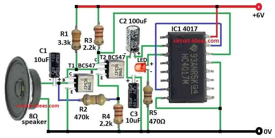
Clap Switch Circuit using IC 4017 turns on ON or OFF with a clap sound.
It uses speaker as microphone.
Speaker and microphone are built same way so speaker can work like microphone in this circuit.
Circuit Working:
Parts List:
| Component Type | Value | Quantity |
|---|---|---|
| Resistors (All resistors are 1/4 watt) | 3.3k | 1 |
| 470k | 1 | |
| 470Ω | 1 | |
| 2.2k | 2 | |
| Capacitors | Electrolytic 10μF | 2 |
| Electrolytic 100μF | 1 | |
| Semiconductors | IC 4017 | 1 |
| Transistors BC547 | 2 | |
| LED any 5mm 20mA | 1 | |
| Speaker 8Ω | 1 |
This circuit is clap switch with 4017 decade counter IC.
It also uses speaker like microphone.
Each clap turn ON the next LED.
LEDs glow one by one with each clap.
How it work:
Speaker act like microphone and a clap make small voltage in speaker.
Transistor T1 BC547 get this voltage from capacitor C1 and make it stronger.
Resistor R2 set working point of T1.
Capacitor C2 stop DC from going next part.
Transistor T2 BC547 work like Schmitt trigger.
It switches fast when voltage reach certain level.
This help reduce noise.
R3 and R4 set trigger levels.
Output from T2 goes to pin 14 which is the clock pin of 4017 IC.
Pin 15 is reset pin and when its low the counter goes to output 0 of pin 3.
R5 keep reset pin high so IC keeps working.
Pin 16 is inhibit pin but not used here.
4017 IC has 10 output pins from pin 3 to pin 11 and with each clap the clock pulse next pin goes high.
Output pin connect to LED with resistor R5.
LED turns ON when output is high.
No clap then pin 14 low and T2 output is low and first LED pin 3 is ON.
Clap makes voltage spike which goes through T1 and T2 to pin 14.
It gives clock pulse and counter move to next output pin 4 and next LED turns ON.
Formulas:
BC547 Biasing Resistors:
To make BC547 work right use proper resistors.
Base current IB can be found using:
IB = (Vin − VBE) / RB
where,
- VBE is about 0.7V for silicon transistor.
4017 IC Timing:
To control how fast LEDs switch we used resistor and capacitor.
Time (T) = 0.7 × RT × CT
where,
- RT is timing resistor
- CT is timing capacitor
This sets pulse length or gap between claps.
LED Current Limiting Resistor:
To protect LED use resistor in series:
RLED = (Vcc − VLED) / ILED
where,
- Vcc is the power voltage
- VLED is the voltage drop across LED
- ILED is the current needed for LED
Design Notes:
When making clap switch choose right values for resistors and capacitors.
This ensures circuit works well, hears claps and lights LEDs in order.
No exact math are always needed but proper design needed for good working.
How to Build:
To build a Clap Switch Circuit using IC 4017 we need to follow the below mentioned connections process:
- Connect pin 2 of IC 4017 to C2 and C3 other sides of capacitor goes to ground.
- Connect pin 3 of IC 4017 to LED and R5 other side to ground.
- Join pin 7 and pin 15 together.
- Connect pin 8 and pin 13 to ground.
- Connect pin 16 to +6V supply.
- Connect pin 14 between T2 collector and resistor R3.
- T1 collector goes to one side of R1 and other side of R1 to +6V.
- T1 base connect to C1 and one wire of 8Ω speaker and other wire of speaker to ground.
- T1 emitter goes to ground.
- T2 collector connects to one side of R3 other side to +6V.
- T2 base connects to R1 and T1 collector.
- T2 emitter goes to ground through R4.
- R2 connect between T1 base and point between T2 emitter and R4.
Extra Notes:
- Speaker is not best as mic.
- Better to use condenser mic which is more sensitive to sound.
- Background noise can make circuit too sensitive.
- Can change resistor values to reduce noise effect.
- LED only stays ON for short time and to keep it ON longer we need extra circuit.
Conclusion:
Clap Switch Circuit using IC 4017 switches turns ON / OFF device by sound.
Speaker can work but condenser mic is better with more reliable and sensitive.
Speakers are not made for sound detection but it can get triggered by noise.