DC Voltage Doubler Circuit is like small power booster.
It takes normal battery power and make almost double.
It use smart parts like diodes and capacitors and they work like tiny switch and small electric bucket.
Sometimes many also use transistor or tiny chip to help.
Imagine electric flow from battery like small stream.
This circuit cut stream in pieces and then fix it by making it flow strong again like a double power coming out.
Circuit Working:
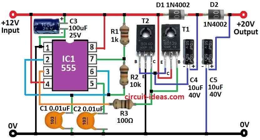
Parts List:
| Category | Part Description | Quantity |
|---|---|---|
| Resistors (All resistors are 1/4 watt) | 1k | 1 |
| 10k | 1 | |
| 100Ω | 1 | |
| Capacitors | Ceramic 0.01µF | 2 |
| Electrolytic 100µF 25V | 1 | |
| Electrolytic 10µF 40V | 2 | |
| Semiconductors | IC 555 | 1 |
| Transistors T1 BD139 and T2 BD140 | 1 each | |
| Diodes 1N4002 | 2 |
This circuit uses 555 IC to make square wave signal.
Then it goes to last part with two transistors T1 and T2.
Real voltage boost happen with four parts: D1, D2, C4 and C5.
The 555 IC work as astable multivibrator it give about 8.5kHz signal.
This signal control T1 and T2 and turn them ON and OFF again and again.
How voltage doubling happen:
When signal is low:
T1 is OFF and T2 is ON.
C4s negative side connects to ground and it charge through D1.
When signal is high:
T1 is ON T2 is OFF
C4 cannot discharge because D1 blocks it.
Now C5 charge from C4 plus power supply of 12V
So C5 get more voltage like 12V + charge from C4.
Normally output is around 20V if current not more than 70mA.
But really it stays near 18V.
Efficiency is not so great but about 32%.
If one take less current then voltage goes little higher.
If one want steady voltage then can add 3 pin voltage regulator IC.
But be careful, regulator IC also use current.
Total current (load + IC) should not go over 70mA.
Formula:
To get more DC voltage from small one we can build a voltage doubler circuit.
Main idea is to use 555 IC to make square wave and use that with transistors, diodes, capacitors and resistors to double voltage.
There is a simple formula to imagine output voltage (Vout):
Vout = 2 × Vin − VD − Vdrop
where:
- Vin is the input voltage
- VD is voltage drop on diodes which is usually around 0.7V each
- Vdrop is drop from transistors or other parts
This formula give rough idea how much voltage one will get at output.
But to make this work correct all the time one needs to choose parts carefully and connect them the right way.
How to Build:
To build the DC Voltage Doubler Circuit we needs to follow the below mentioned assembling steps:
Gather All Parts Ready:
- Collect all the parts one needs and check they match what circuit design says.
Build the 555 Timer Circuit:
- Use 555 IC to make astable circuit.
- Check 555 datasheet and connect resistors and capacitors to get around 8.5kHz frequency.
Add Transistors T1 and T2:
- Connect T1 and T2 to 555 output.
- Be sure they are wired right and follow their datasheet for proper pin connections and biasing.
Hook Up Diodes and Capacitors (D1, D2, C4, C5):
- Now connect D1, D2 and capacitors C4, C5.
- Watch carefully the diodes and capacitors have polarity and connect the correct side.
Test the Circuit:
- Turn ON the power.
- Check voltage across C5 which should be around 20V if input is 12V.
Fix All Wires:
- If working fine protect the wires.
- Be sure nothing is loose or shorted.
Check with Load and Adjust if Needed:
- Try different loads to see if voltage stays stable.
- Adjust things if output is not what one wants.
Note:
- If we follow each step slowly and connect things the right way the voltage doubler should work fine!y.
Conclusion:
A DC Voltage Doubler is small circuit that take low voltage and make it almost double.
It uses diodes, capacitor, and some switching parts to do this job.
This circuit is useful when anyone needs more voltage but only have small power source.
It works simple with no need of big transformers or hard wiring but with just smart setup with few parts are needed.