Simple Door Open Alarm Circuit using Reed Switch uses reed switch which makes alarm sound when door opens.
This simple circuit help protect door from people not allowed.
It have reed switch, transistors, resistors, buzzer, diode and LED.
Reed switch control power to alarm.
Circuit Working:
Parts List:
| Category | Description | Quantity |
|---|---|---|
| Resistors | 1k 1/4 watt | 1 |
| 2.2k 1/4 watt | 1 | |
| Semiconductors | Transistors BC547 | 2 |
| Diode 1N4007 | 1 | |
| Red LED 5mm 20mA | 1 | |
| Buzzer 5V | 1 | |
| Reed switch | 1 |
Reed switch work like magnetic door sensor.
Inside it have two metal pieces like switch.
When magnet (ON door) comes close it pull metal pieces together.
This close the circuit and switch is ON when door is closed.
When door is open the magnet move away and pull goes away and the metal pieces separate.
Now switch is OFF and the circuit break.
Circuit use two transistors Q1 and Q2 to control buzzer alarm.
When door is closed the reed switch is ON and small current goes to Q2.
Q2 turn ON and grounds the circuit and the buzzer stays quiet.
When door opens the reed switch goes OFF with no current goes to Q2.
Q2 turn OFF and now Q1 get more current from resistor and turn ON.
Q1 let power go to buzzer and buzzer makes sound.
Transistors act like switch and controls alarm based on reed switch signal.
Formulas:
This circuit uses Reed switch, LED, buzzer and transistor.
When door opens it turn ON LED and buzzer.
Reed switch act like magnetic sensor which detects door open or close.
Design Tips and Formulas:
1. Base Resistor RB for BC547:
Need base resistor to turn ON transistor properly.
Formula:
RB = (Vin − VBE) / IB
where:
- Vin is the 5V input
- VBE is 0.7V for BC547
- IB is the base current
2. LED Resistor RLED:
Need resistor to protect LED from too much current.
Formula:
RLED = (Vsupply − VLED) / ILED
where:
- Vsupply is the 5V
- VLED is the 2V for red LED
- ILED is 20mA for LED current
This simple circuit give sound and light when door opens.
We can change design based on our needs.
How to Build:
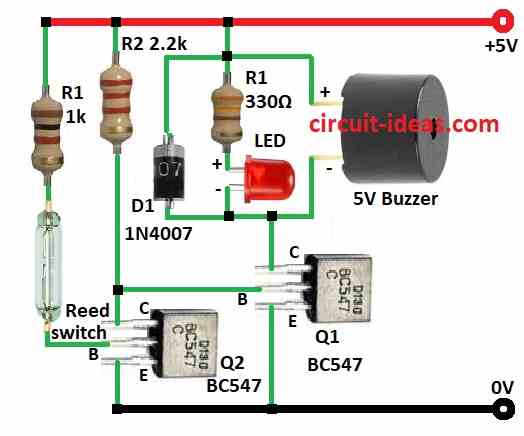
To build a Simple Door Open Alarm Circuit using Reed Switch follow the below mentioned connections steps:
- Put all parts same like in diagram.
- Connect Q1 collector between buzzer negative pin and LED cathode.
- Connect Q1 base between resistor R2 and Q2 collector.
- Connect Q1 emitter to ground.
- Connect Q2 collector to resistor R2 and then to +5V.
- Connect Q2 base to reed switch and resistor R1 and then to +5V.
- Connect Q2 emitter to ground.
- Connect red LED and resistor R1 from Q1 collector to +5V.
- Connect diode D1 anode to Q1 collector and cathode to +5V.
- Connect buzzer positive to +5V and buzzer negative to Q1 collector.
Conclusion:
This Simple Door Open Alarm Circuit using Reed Switch and magnet knows when door opens.
When door is closed magnet closes the circuit with no sound.
When door open the magnet moves and circuit break and buzzer makes sound.
Be careful and safe when building this circuit.
Leave a Reply