This Simple Electronic Component Tester Circuit works like doctor for ones electronic parts.
Before we make any cool thing one can use this tester to check parts like resistor, capacitor, transistor and many more.
Tester shows if the parts are good or bad so we do not waste time with broken parts in our project.
This type of circuit is very useful for hobby people and anyone who like to have a fun with electronics.
Circuit Working:
Parts List:
| Category | Component | Quantity |
|---|---|---|
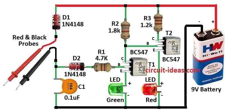
| Resistors | 4.7k 1/4 watt | 1 |
| 1.8k 1/4 watt | 1 | |
| 1.2k 1/4 watt | 1 | |
| Capacitor | Ceramic C1 0.1µF | 1 |
| Semiconductors | Transistor BC547 | 2 |
| Diodes 1N4148 | 2 | |
| LED Green 5mm 20mA | 1 | |
| LED Red 5mm 20mA | 1 | |
| Red Meter Probe | 1 | |
| Black Meter Probe | 1 | |
| Battery 9V | 1 |
This small device is made to check if electronic parts like resistor, capacitor and even ICs are good or bad before one solders them.
It makes testing easier but not like using big multimeter every time.
It have got two LED lights which show if part is working or not like green for good and red for bad.
The circuit is simple but works well.
It uses two NPN transistors to control the LEDs.
When one turn it ON the red LED turns ON first because T2 gets power through R2.
Green LED stays off because T1 is not getting any base power.
Now when we put a component between the probes it connects the circuit through which T1 gets power through R1 and turns ON.
When T1 turns ON green LED lights up and red LED goes OFF because T1 is pulling T2s base to ground.
That means the part is okay.
So green light only turns ON when good part is placed
If the part is broken then nothing happens green LED stays OFF and red LED stays ON by information the parts are bad.
Formulas:
Using parts like resistor, LED and transistor one can build easy circuit to test basic components like resistors, LEDs and maybe some more.
This circuit uses LEDs to show if the parts are good or not and transistors work like ON/OFF switch.
Current through LED:
By using ohms law to check LED gets correct current:
ILED = (VBattery − VLED) / R
where,
- VBattery is 9V
- VLED is 2V
- R is resistor value
Switching Transistor:
Need to give base enough current to turn transistor fully ON for saturation:
IB = (VBase − VBE) / RBase
where,
- VBase is 9V
- VBE is 0.7V
Current through Resistor:
Again use ohms law:
IR = VBattery / R
This simple tester circuit can help one to check if resistor or LED is working or not.
Two BC547 transistors control the LEDs like switch and they turn LED ON or OFF based on parts condition.
Circuit is also protected and works fine with this setup.
How to Build:
Below mentioned are the steps to build a Simple Electronic Component Tester Circuit:
Connect the Parts:
- First put all parts on breadboard or PCB same as in circuit diagram.
Add Power:
- Connect 9V battery with positive wire to circuit and negative to ground.
Check LEDs:
- Turn ON the power.
- Red LED should turn ON to show power is coming and green LED stay OFF in beginning.
Calibration (Optional):
- If we use potentiometer then turn it slowly till green LED just start flashing when probes are not touching anything this will help for better testing.
Test Components:
- Now take a part like resistor or LED and touch its legs to the probes.
- If green LED lights up it part is good.
- If red LED stays ON and green stays OFF its part is bad.
Final Testing:
- When everything works fine we can now use this tester to check electronic parts before putting them in out project.
Note:
- This is simple tester circuit if anyone needs more features can change or add parts to make it better.
Conclusion:
Simple Electronic Component Tester Circuit is very useful tool for people who like to work with electronics or do small projects.
It help one to check if parts are good or bad before it uses them so that we do not waste time later fixing things.
With simple design and basic parts this tester can save us from big trouble and make sure our circuit work properly.
Leave a Reply