To begin with, this Simple FET Preamplifier Circuit works like super booster for small sound, as it uses special transistor, FET to make quiet sound go more loud.
Also, this circuit is very good, because it uses two kind of transistors N channel FET and PNP bipolar, together they make sound strong and not bad.
So even very tiny sound we hear can be nice and clear.
Circuit Working:
Parts List:
| Components | Values | Quantity |
|---|---|---|
| Resistors (All resistors are 1/4 watt unless specified) | 1M | 1 |
| 5.6k | 1 | |
| 18k | 1 | |
| 15k | 1 | |
| 680Ω | 1 | |
| Capacitors | Ceramic C1 0.22µF | 1 |
| Electrolytic C2 100µF 25V | 1 | |
| Electrolytic C3 10µF 25V | 1 | |
| Semiconductors | Transistor BC557 | 1 |
| FET BFW11 | 1 |
This preamp design is useful in many ways, as it can use normal PNP transistors like BC557 or BC558 which depend how much gain one needs.
How loud it make gain come from feedback parts with R4 and R5 value the gain will be around 20.
Also, the input of preamp is sensitive so it work easy with MIC and ceramic pickup.
Formulas:
FET BFW11 is good choice for low noise amplifier because it has high input impedance and low noise.
FET Biasing:
To make BFW11 FET work good we need to give it right bias, this mean we give correct DC voltage (VGS) between gate and source.
Hence, first choose is how much current (IDQ) should go in FET and for that use ohms law to find resistor RG:
RG = VGS / IDQ
Check FET datasheet and choose VGS value for this circuit.
Source Resistor (RS):
To control gain and keep DC stable we must put resistor RS with FET source pin.
Use formula to find RS:
RS = 1 / gm
here,
- gm shows how strongly the FET controls current and this property is called transconductance.
Capacitors for Signal:
We use capacitors to send AC signal in and out and to stop DC and to find right capacitor value use this formula:
XC = 1 / (2πfC)
where,
- C is capacitor value
- f is frequency
- XC is how much the capacitor blocks signal reactance
Notes:
Right values of resistors and capacitors depend on the circuits gain, frequency and bias; try first on breadboard and then check if it work.
Change part values if needed after testing or simulation, also this is just starting idea for using BFW11 FET preamp.
We can change it based on what one need for their project.
How to Build:
To build a Simple FET Preamplifier Circuit we need to follow the below steps:
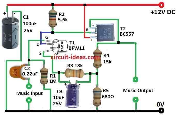
Connect the Parts:
- First, connect FET gate to ground using C2 capacitor and music input wire.
- Next, connect source of FET to resistor R3 and then to C3 capacitor.
- After that, connect drain of FET to base of BC557 transistor and to R2 resistor point.
- Then connect R4 15k and R5 680Ω between collector of BC557 and ground and now connect emitter of BC557 to positive power supply.
Add Capacitors:
- Next, connect C1 100μF to one leg of +V other leg to ground.
- After that, connect C2 0.22μF between FET drain + music input and ground.
- Now connect C3 10μF between FET source and R3 18k.
Input and Output:
- Input signal goes between gate of FET and ground and output signal comes from collector of BC557 transistor.
Testing the Circuit:
- Power the circuit with correct voltage and then give input like microphone or ceramic pickup to check if preamp works.
- Also, we can change R4 and R5 values if need more or less gain.
Important:
- Be sure all parts connect in correct way and follow correct polarity for capacitors and power.
Conclusion:
Overall, this Simple FET Preamplifier Circuit is easy to build and works good for audio use; it uses N Channel FET and PNP transistor so it gives high input impedance with low output impedance and stable gain.
Hence, because of this, it work well with microphones and other audio source, also it give sensitive and steady sound boost.
Leave a Reply