This Simple Entrance Alarm Circuit protects a door or entryway; it produces a loud sound when someone passes through an invisible IR light beam.
Furthermore, it works good at day and night by not giving much wrong alarm; also the circuit is simple and good for hobby people during nighttime.
Circuit Working:
Parts List:
| Components | Values | Quantity |
|---|---|---|
| Resistors | 100Ω 1/4 watt | 2 |
| Preset 1k | 1 | |
| Semiconductors | Photo transistor L14F1 or similar type | 1 |
| Transistor BC547 | 1 | |
| LED Green 5mm 20mA | 1 | |
| LED Red 5mm 20mA | 1 | |
| IR transmitter LEDs | 3 | |
| Buzzer | 1 |
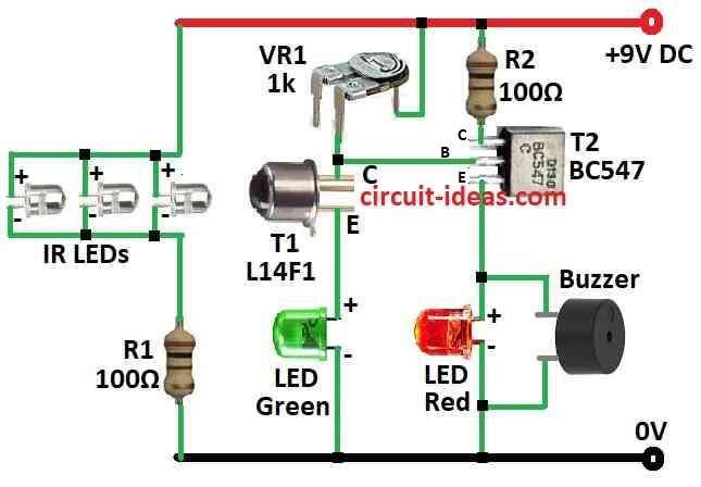
This circuit use IR diodes to send out infrared light all time but not like remote that send in short pulses, as it uses one NPN Darlington phototransistor to see the light.
The L14F1 is very sensitive phototransistor with big gain, its collector connects to positive side through VR1 and emitter have green LED to show standby.
The base of T1 is not directly connected because light enters through the T1 window and strikes the base region, activating it.
As the light intensity increases, T1 conducts more and works more effectively.
Moreover, T2 work as driver for alarm and its base connect to T1s collector so it depends on T1 working and when IR light fall on phototransistor it works and pull T1 base to ground and T1 stay OFF
In this case the red LED and buzzer ON T2 emitter as it stays OF and when someone break the IR beam the T1 stops working and so its collector voltage goes up.
Then T2 turns ON and red LED + buzzer also turn ON and we can build this circuit on small PCB board.
Put R1 and IR LEDs on different small board and keep IR LEDs on one side of door and phototransistor on other side.
Point IR light properly to phototransistor so buzzer stays quiet when no one passes.
Wave hand in middle to test and check buzzer should make sound and use VR1 to adjust T2 base bias, so buzzer stays OFF when no one is around.
How to Build:
To build a Simple Entrance Alarm Circuit we need to follow the below mentioned steps:
Make IR LED Board:
- First, put IR LEDs and one resistor R1 on different small board.
- Resistor value depend on which IR LED we will use and this board will send invisible IR light.
Make Phototransistor Board:
- Next, fix phototransistor L14F1 on other board and ensure IR light from LED board connects straight to this phototransistor.
Build Main Circuit:
- Put phototransistor L14F1 on main PCB board and then connect its collector to positive side with VR1 preset.
- Also, connect emitter to ground.
Connect LEDs and Buzzer:
- Green LED connects to emitter of phototransistor which will show standby mode and red LED and buzzer connects to emitter of another NPN transistor T2 for alarm.
Connect T2 Base:
- Connect base of T2 to collector of phototransistor T1 and this will decide when alarm will turn ON.
Give Power:
- Connect battery or power to circuit and be careful with plus and minus.
Adjust VR1:
- Use VR1 to set T2 base level and buzzer should stay OFF when no one passes.
Test the Circuit:
- Wave hand in front of IR beam and if circuit work then buzzer will make sound.
Mount Everything:
- Put full circuit in good box and be sure IR LED board and phototransistor board face each other.
- Line up beam properly.
Finish:
- Tie all the wires and parts and check they are safe now we can see IR beam alarm is ready to use!
Note:
- Be careful and always turn OFF the power before changing wires, also, check that all parts connect securely and fit tightly.
Conclusion:
To conclude, this Simple Entrance Alarm Circuit is easy and useful way to protect door or entrance, as it work good in day and night and does not gives any wrong alarms.
Finally, because circuit is simple it is very good small project for hobby people who like home security ideas.