Imagine our devices as a little translator!
This Simple IC 555 PWM Generator Circuit work like that translator but for signal and electricity, as it uses one special chip called as IC 555 to take message and make it like pulse signal.
Also, this pulse signal can help control things like light brightness or motor speed and circuit change the pulse size and we call it a duty cycle to send the messages.
So maybe we do not see real message but this circuit use pulse to do many cool electronic stuff.
Circuit Working:
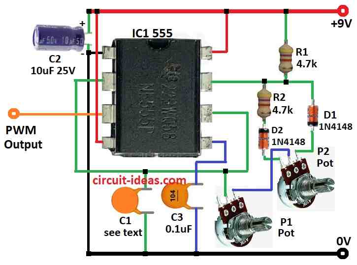
Parts List:
| Components | Values | Quantity |
|---|---|---|
| Resistors | 4.7k 1/4 watt | 2 |
| Potentiometer see text | 2 | |
| Capacitors | Ceramic C1 see the text | 1 |
| Ceramic 0.1µF | 1 | |
| Electrolytic 10µF 25V | 1 | |
| Semiconductors | IC 555 | 1 |
| Diodes 1N4148 | 2 |
To begin with, this circuit make pulse using 555 IC through which we can change PWM cycle, also it work like astable multivibrator that mostly gives 50% PWM cycle.
One big change from normal 555 circuit is special resistors between pin 6 and 7 which uses P1, P2, R2, D1 and D2.
D1 and D2 help set charge time for capacitor C1 and make 50% PWM when everything is normal, so we call the PWM duty cycle ‘n.’, as it changes when we turn P1 and P2 and we can calculate it with a formula.
If P2 is zero (so n = 100%) we can also use another formula to find frequency.
Formulas:
Understand PWM (n) Formula for 555 PWM Circuit.
Using 555 Timer as PWM Generator:
555 IC is small chip and it can make PWM signal when we connect it in special way, in astable mode it will give square wave again and again non-stop.
We can control duty cycle (by how long it will be ON or OFF) by choosing right parts, as they work together to decide duty cycle.
PWM Duty Cycle Formula: n = 1 + (P2 / P1)
where:
- n is duty cycle example: n = 2 means 50% ON and 50% OFF
- P1 is the value of resistor P1
- P2 is the value of resistor P2
How to Build:
To build a Simple IC 555 PWM Generator Circuit we need to follow the below mentioned connections steps:
How to Connect 555 Timer for PWM:
- First, connect pin 1 to ground and pin 8 to VCC of positive power.
- Next, connect pin 4 to VCC also this will turn OFF the reset function.
- Now join pin 2 and pin 6 together.
- Also, between pin 6 and pin 7 put R2 4.7k and D1 1N4148 in series, also put D2 1N4148 in parallel with D1.
- Then connect C2 10µF capacitor to positive power supply.
- After that, connect pin 5 with C3 0.1µF capacitor to ground.
- Pin 3 is the output and this is where we can get PWM signal.
- Now connect pin 6 to pin 2 using P1 and P2 in series and then turn P2 to change PWM value of output wave.
Note:
- This circuit gives about 50% PWM by default and we can change PWM by adjusting P2 to match what we need.
Conclusion:
Overall, Simple IC 555 PWM Generator Circuit is very useful and popular circuit, as it uses 555 timer IC to make PWM signals.
Furthermore, we can change PWM easily so this circuit can do many jobs like control motor speed, make LED light dim or bright and even make sound tones.
Leave a Reply