Think of flashing lights in a line but with LEDs and not with bulbs!
This LED Chaser Circuit using Transistors makes LEDs light up one by one like running.
It uses small switches called transistors to control LEDs.
This circuit is good for beginners and is fun way to learn how transistors work!
Circuit Working:
Parts List:
| Component Type | Description | Quantity |
|---|---|---|
| Resistors (All resistors are 1/4 watt unless specified) | 22k | 5 |
| 470Ω | 5 | |
| Capacitors | Electrolytic 22µF 25V | 6 |
| Semiconductors | Transistors BC547 | 5 |
| LEDs any 5mm 20mA | 5 |
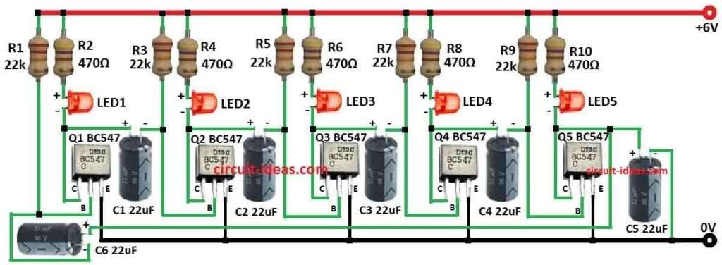
This is a basic LED chaser circuit using 5 NPN BJT transistors Q1 to Q5.
Circuit runs on 6V power.
Each transistor has one capacitor C1 to C5 and some resistors R1 to R10 on base and collector.
When power is ON capacitors charge through resistors.
As capacitor charges voltage at transistor base goes up.
When voltage reaches 0.7V transistor turns ON and current flows, LED lights up like LED1 to LED5 through resistor R1, R3, R5, R7, R9.
When transistor is ON capacitor starts discharging through collector-emitter path like through R7 and C3.
As it discharges the base voltage drops.
When voltage goes below 0.7V then transistor turns OFF and LED goes OFF.
Each capacitor has different value so charge/discharge times are different.
This makes LEDs turn ON and OFF one by one like chasing lights.
Formulas:
Making many levels of LED chasing with transistors is common in LED chaser design.
We use a simple formula to plan the chasing speed:
LED Chaser Speed (Chasing Rate):
Use capacitor charge/discharge time to find speed:
τ = R × C
where:
- τ is time constant
- R is resistor value
- C is capacitor value
f = 1 / 2τ
This gives LED chasing frequency.
Change R or C to make chase faster or slower.
This formula helps design basic LED chaser.
To make it work well test and design carefully.
How to Build:
To build a LED Chaser Circuit using Transistors follow the below mentioned connections steps:
LED Chaser Circuit Connections:
- Q1 base goes to R1 22k, collector to R2 470Ω and LED1 and emitter to ground.
- Q2 base goes to R3 22k, collector to R4 470Ω and LED2 and emitter to ground.
- Q3 base goes to R5 22k, collector to R6 470Ω and LED3 and emitter to ground.
- Q4 base goes to R7 22k, collector to R8 470Ω and LED4 and emitter to ground.
- Q5 base goes to R9 22k, collector to R10 470Ω and LED5 and emitter to ground.
Capacitor Connections:
- C1 connects one side to Q1 collector and other side to Q2 base
- C2 connects one side to Q2 collector and other side to Q3 base
- C3 connects one side to Q3 collector and other side to Q4 base
- C4 connects one side to Q4 collector and other side to Q5 base
- C5 connects one side to Q5 collector and other side to ground
- C6 connects one side to Q1 base and other side to Q5 collector
Note:
- There are advanced LED chasers with speed control, color LEDs and more patterns.
- But this simple circuit is good to learn basics.
Conclusion:
This easy LED Chaser Circuit using Transistors shows chasing lights using transistors.
The project is with simple parts and easy to build.
It is an great project for beginners to learn how transistors work.
The startup circuit/device will indicate that multiple positions are active. Each time the battery is connected, a different sequence of flashes will be displayed. The effect will not follow a fixed pattern, nor will it repeat a single empty state. The sequence will be random, with each variation appearing distinct.
Thank you for your feedback. You may be correct, however the circuit will still produce the sequential LED chasing effect, right?