This Simple LED Voltmeter Circuit is like small battery checker but with cool lights.
Not like phone bar this one is used in many tiny lights like LEDs to show how much battery is still there.
More lights turn ON when battery is more full and each light become ON at different voltage.
It also use special diodes called Zener and some resistors to give right power to lights so they shine good.
So just take a small look and we can know how much power is left in the battery
Circuit Working:
Parts List:
| Category | Description | Quantity |
|---|---|---|
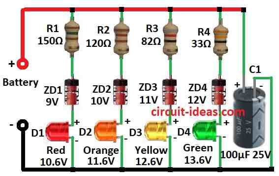
| Resistors (All resistors are 1/4 watt) | 150Ω, 120Ω, 82Ω, 33Ω | 1 each |
| Capacitor | Electrolytic 100µF 25V | 1 |
| Semiconductors | Zener diode 9V, 10V, 11V, 12V | 1 each |
| LEDs 5mm 20mA (Red 10.6V, Orange 11.6V, Yellow 12.6V, Green 13.6V) | 1 each |
This is simple LED voltmeter it checks how much charge is in lead acid or tubular battery.
It have got four small lights like LEDs to show battery voltage.
Lead acid battery are full at 13.8V and tubular one are full at 14.8V.
This voltmeter uses four Zener diodes each one turn ON LED when voltage hit the diodes breaking point.
But for Zener to break and work the voltage must go 1.6V higher than its number.
If battery have 13.6V or more then all Zeners break down and all lights will turn ON.
If battery goes down below 10.6V then no lights will show and all will be OFF.
So lights turn ON or OFF one by one depends how much voltage battery have.
Formula:
This circuit uses resistors and LEDs to show battery voltage.
When voltage across resistor reach certain point then LED will turn ON.
Resistors divide battery power.
We can find voltage on each resistor using this formula:
V = I * R
where:
- V is voltage on resistor
- I is current going through
- R is resistor value
Current connects same through all resistors and LEDs because they are in series.
When LED gets current it drop some voltage and this is called forward voltage.
Red LED usually drop around 1.8V.
To know voltage across LED uses this formula:
V = Vf + Vr
where:
- V is voltage across LED
- Vf is LED forward voltage
- Vr is voltage drop on resistor with LED.
Capacitor C1 help remove noise from battery voltage.
When we choose capacitor think about what kind of filtering we need.
How to Build:
To build a Simple LED Voltmeter Circuit follow the below mentioned steps:
- First connect battery positive side to one end of resistor.
- Then connect other side of resistor to long leg anode of first LED.
- Now connect short leg cathode of first LED to long leg anode of first Zener diode.
- After that connect short leg cathode of first Zener to long leg anode of second Zener diode.
- Do same steps for next LEDs and Zener diodes and connect them one after another in line.
- At end connect short leg cathode of last Zener diode to battery negative side.
Note:
- Before using with battery test circuit with power supply.
- If LEDs do not turn ON at right voltage then change resistor values to fix.
Conclusion:
Simple LED Voltmeter Circuit is cheap and easy way to check the power voltage.
It uses LEDs and Zener diodes to show voltage with lights so we can see voltage level easily.
It is very useful in many things like cars, battery chargers and other devices where we need to watch voltage.
This circuit give simple and good way to know if voltage is high or low.
Leave a Reply