This article for Simple Low Battery Indicator Circuit using Two Transistors tell how to make small circuit for battery device.
When battery goes low it uses only few parts like two transistors to turn ON one LED light.
So this way we can know when to change battery before device stop working.
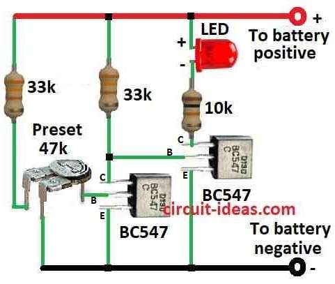
Circuit Diagram:
Parts List:
| Category | Description | Quantity |
|---|---|---|
| Resistors | ||
| 33k 1/4 watt | 2 | |
| 10k 1/4 watt | 1 | |
| Preset 47k | 1 | |
| Semiconductors | ||
| Transistors BC547 | 2 | |
| LED 20mA 5mm | 1 |
Idea of Circuit:
Before people used 741 IC and 555 IC for low battery check.
These ICs are famous to work when battery is low.
But here we show different and cheaper way.
This circuit use only two NPN transistors to give low battery signal.
Why Transistor is Better Than IC:
This two transistor circuit take very small current.
It uses less power than IC and IC 555 take around 5mA and IC 741 take 3mA but this circuit only need 1.5mA.
So it is good for small battery like 9V battery and when we want less power used in standby.
Work Even with 1.5V Battery:
One more good thing is this circuit work even with just 1.5V.
IC circuit do not work with so low voltage so this circuit is better.
In this circuit two transistors work as inverter and voltage sensor.
There is 47k preset like resistor we can adjust and it sets the voltage level when first transistor are left side will stop.
When battery voltage is okay then left transistor works and right transistor is OFF and so LED is OFF.
When battery goes low left transistor stop working and then right transistor start fast and LED turns ON.
So LED turning ON is the sign that battery is low now.
Formula:
This low battery circuit uses two transistors and one resistive divider.
The resistive divider main job is to give reference voltage for checking battery level.
To make resistive divider work we need to use one important formula:
Resistive Divider Formula:
Vout = VBattery × R2 / (R1 + R2)
where:
- VBattery is the battery voltage.
- R1 is resistor connected to battery side.
- R2 is resistor connected to ground side.
With this formula and knowing how circuit works we can make good low battery indicator using only two transistors.
Change resistor values and components as needed for different battery type or for our own project.
How to Build:
To build the Simple Low Battery Indicator Circuit using Two Transistors one should go through the following steps:
- First connect battery positive (+) to circuit.
- Then connect battery negative (–) to ground.
- Connect collector of first NPN transistor to battery positive (+).
- Connect emitter of first NPN transistor to base of second NPN transistor.
- Now connect collector of second NPN transistor to battery positive (+) also.
- Connect emitter of second NPN transistor to ground.
- Connect base of first transistor to middle pin wiper of 47k preset.
- One side of 47k resistor goes to base of first transistor.
- Other side of 47k resistor goes to ground.
- Now between second transistor collector and battery positive, connect LED and its resistor in series.
How to Set the Voltage Level:
- Use 47k preset to set the voltage level for low battery signal.
- This preset will control when LED will turn ON.
- When battery voltage goes down below the set level then LED will light up.
- We can change the preset to make the circuit work with different battery levels.
Conclusion:
Many electronic devices use this type of Simple Low Battery Indicator Circuit using Two Transistors to warn when battery is low.
We can change the 47k preset to make it work for different battery voltage levels.