Op-amps (operational amplifiers) are very important in electronics.
They are used for filtering, amplify signals and analog signal work.
Before using op-amp IC we must test it to ensure it works good and correct.
To check op-amp fast and easy we have made a Simple Op-amp IC Tester Circuit
Op-amp is like voltage comparator and it has two inputs one is inverting (-) and other is non-inverting (+).
If non-inverting (+) voltage is more than inverting (-) then output is HIGH.
If inverting (-) voltage is more than non-inverting (+) then output is LOW.
Op-amps have high gain so people use them to amplify voltage.
Some op-amps have one comparator and some have many like LM741.
This article show simple circuit for testing op-amp using LM741 and with some basic parts.
Circuit Working:
Parts List:
| Component | Value | Quantity |
|---|---|---|
| Resistors | ||
| 1k 1/4 watt | 1 | |
| 4.7k 1/4 watt | 1 | |
| 10k 1/4 watt | 4 | |
| Capacitor | ||
| Electrolytic 10µF 25V | 1 | |
| Semiconductors | ||
| IC LM741 | 1 | |
| Diodes 1N4148 | 2 | |
| LED any 5mm 20mA | 1 |
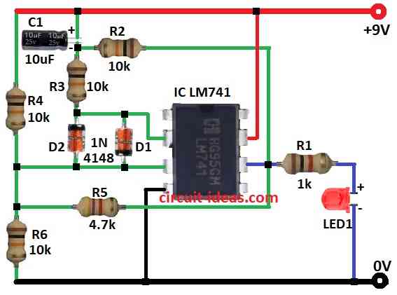
This simple tester circuit check if LM741 op-amp is working or not.
The circuit uses LM741 op-amp, some resistors, diodes, one capacitor, LED and 9V battery.
Circuit uses only one 9V power to keep it easy.
Put LM741 op-amp in right position on the board.
If op-amp is good then LED will blink.
If op-amp is bad then LED stay always ON or always OFF.
Circuit work like this:
When power is ON op-amp give square wave at output and this make LED blink.
At start pin 3 (+) voltage is more than pin 2 (-) so output (pin 6) is HIGH.
Capacitor C1 charge through resistor R2.
When voltage at pin 2 (-) get more than pin 3 (+) then output goes LOW.
Then capacitor C1 discharge and again pin 3 (+) get more voltage and so output goes HIGH again.
This charging and discharging keep happening and output goes HIGH and LOW by making square wave.
Because of square wave the LED blink again and again.
So if LED blink then op-amp is OK and If does not blink then op-amp is bad.
Formulas:
These formulas help understand how LM741 op-amp work in the simple tester circuit:
1. Voltage Divider Formula:
This gives reference voltage to op-amp non-inverting pin (+):
Vref = Vin × R2 / (R1 + R2)
where,
- Vref is the voltage at pin (+)
- Vin is the input voltage for 9V battery
- R1, R2 are the resistors in voltage divider
2. LED Current ohms law:
To check LED getting right current
ILED = (Vout − VLED) / RLED
where,
- ILED is the current in LED
- Vout is op-amp output voltage
- VLED is the LED forward voltage
- RLED is the resistor with LED
3. Op-Amp Gain (Buffer Mode):
For buffer the output = input so the formulas is:
Gain G = Vout / Vin = 1
4. Capacitor Impedance:
Capacitor block noise is its impedance is:
ZC = 1 / (j × ω × C)
where,
- ZC is the capacitor impedance
- j is the imaginary unit (√-1)
- ω is the 2π × frequency (f)
- C is the capacitor value
Low ZC at high frequency is good noise filter.
5. Diode Voltage Drop:
Diode stop reverse current and voltage drop then we can use this formula:
VD = ID × RD + VD,0
where,
- VD is the total voltage drop
- ID is the current in diode
- RD is the resistance in path
- VD,0 is the forward voltage with 0.7V for silicon diode
These formulas help design and understand how tester circuit work.
How to Build:
To build a Simple Op-amp IC Tester Circuit follow the below mentioned connections steps:
- Connect pin 2 (inverting input) of LM741 to two 1N4148 diodes one forward and other one reverse and one to 10k resistor R3
- Connect other ends of both diodes to pin 3 (non-inverting input) of LM741 and junction point of R4, R5, R6 resistors
- Connect other ends of R6 to ground, R4 to +9V supply and R5 to pin 6 (output) of LM741
- Connect pin 4 of LM741 to Ground
- Connect pin 7 of LM741 to +9V supply
- Connect capacitor C1 between the junction of R2, R3 and +9V supply
- Connect other end of R2 to pin 6 of LM741
- Connect pin 6 (output) of LM741 to Ground through Resistor R1 and then to LED1
Conclusion:
This simple Simple Op-amp IC Tester Circuit is easy to build.
It checks if op-amp is working or not using blinking LED.
If op-amp is good then LED will blink.
If not LED stay ON or OFF.
It tests op-amps basic function by checking input and output voltage control.