Servo motor is small machine part that can turn to exact position and also people use it in many things like robots, CNC machines and factory machines.
Furthermore, this post for Simple Servo Motor Controller Circuit using Arduino show how to control servo motor using Arduino; it also use push buttons, capacitors, resistors and IC 7809 for power.
Arduino Code:
#include <Servo.h>

Servo myservo;  // Create a servo object

int servoPin = 9;  // Pin connected to the servo signal
int button1Pin = 2;  // Pin connected to the first push button
int button2Pin = 3;  // Pin connected to the second push button

int angle = 0;  // Initial servo angle

void setup() {
  myservo.attach(servoPin);  // Attach the servo to the specified pin
  pinMode(button1Pin, INPUT);  // Set the push button pins as input
  pinMode(button2Pin, INPUT);
}

void loop() {
  int button1State = digitalRead(button1Pin);
  int button2State = digitalRead(button2Pin);

  if (button1State == HIGH) {
    angle += 1;  // Increment the angle
    if (angle > 180) {
      angle = 180;  // Limit the angle to 0-180 degrees
    }
  } else if (button2State == HIGH) {
    angle -= 1;  // Decrement the angle
    if (angle < 0) {
      angle = 0;  // Limit the angle to 0-180 degrees
    }
  }

  myservo.write(angle);  // Set the servo's position
  delay(15);  // Delay for smooth movement
}
Code explanation:
- Code set start angle, button pins and servo pin.
- In
setup(), the code sets the button pins as inputs and attaches the servo to the servo pin. - In loop() code check button press.
- Pressing Button 1 increases the angle, while pressing Button 2 decreases the angle.
- Angle stay between 0 and 180.
- myservo.write() set servo to new angle.
Circuit Working:
Parts List:
| Components | Quantity |
|---|---|
| Resistors | |
| 1/4 watt 100k | 2 |
| Capacitor | |
| 100μF 25V | 1 |
| Semiconductors | |
| Arduino Uno board | 1 |
| IC 7809 | 1 |
| Servo Motor | 1 |
| Tactile Switches | 2 |
In this article servo and other parts can get power from 9V using IC 7809 and servo and Arduino must share same ground.
Also, Arduino uses PWM (Pulse Width Modulation) to control servo position and then servo angle changes by pulse width.
After that Write Arduino code to read buttons and move servo, for example press one button servo goes one way and press other the servo goes the other way.
Now, the Arduino checks BUTTON1 and BUTTON2, when the user presses a button, the input pin reads LOW because it connects to ground and when the user does not press a button, the pull-up resistor causes the pin to read HIGH.
Ensure voltage regulator work good with less noise the better servo will work and finally, resistor and capacitor help give clean and steady power to the circuit.
How To Build:
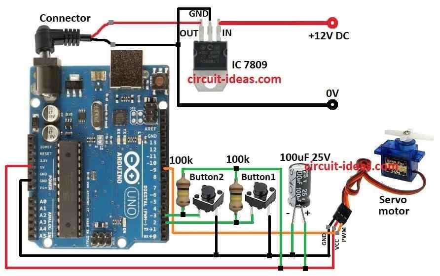
To build a Simple Servo Motor Control Circuit using Arduino following are the connections steps to follow:
- First, collect all parts shown in circuit diagram.
- Next, use IC 7809 to give stable 9V DC to Arduino.
- After that, connect servo ground wire to Arduino ground pin.
- Then connect 5V from Arduino to servo power pin.
- Now connect servo signal pin (PWM) to Arduino pin 9.
- Also, connect 100μF 25V capacitor with one side to 5V and other to ground.
- Then connect button1with one leg to pin 2 and other leg to ground and connect button2 with one leg to pin 3 and other leg to ground.
- Finally, connect 100k resistor between pin 2 and 5V and also connect another 100k resistor between pin 3 and 5V.
Conclusion:
To conclude, this article for Simple Servo Motor Controller Circuit using Arduino show to move servo motor; also by using buttons, resistors, capacitor and IC 7809 make circuit more strong and useful.
Therefore, this circuit is good for many projects.
Leave a Reply