This Simple Siren Circuit article show how to make circuit sound like real siren!
Sound goes up and down fast like police car or ambulance siren.
Making this type of circuit is fun but remember siren are also used when emergency happens.
Circuit Working:
Parts List:
| Category | Description | Quantity |
|---|---|---|
| Resistors | ||
| 47k 1/4 watt | 2 | |
| Capacitors | ||
| Ceramic 0.01μF | 1 | |
| Electrolytic 2.2μF 16V | 1 | |
| Electrolytic 100μF 16V | 1 | |
| Semiconductors | ||
| Transistor BD140 | 1 | |
| Transistor BD139 | 1 | |
| Push Button | 1 | |
| Speaker 8Ω | 1 |
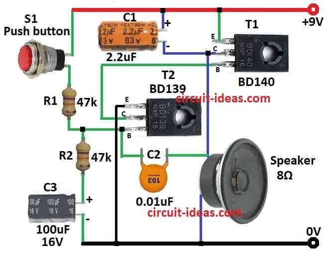
This circuit uses generator with both PNP and NPN transistors to make siren sound.
Transistors work together like a team to make sound keep going and this is called a free running multivibrator.
Capacitor C2 can make one steady sound when connect to power line.
But in this article we want siren sound which is not same sound all time.
So we put RC circuit with resistor R2 to make sound go up and down.
When we press switch S1, capacitor C1 charges slowly through R1 until it reaches about 4V.
As voltage goes up the time at R2 and C2 point get shorter so sound frequency goes higher.
When we let go switch S1 then capacitor C1 drain slowly so sound goes lower.
Because of this waveform look like sawtooth.
Speaker make rising or falling tone which depends if switch S1 is pressed or not.
Formulas:
Main goal of this transistor siren circuit is to make sound like real siren with frequency that can change.
This type of circuit uses two transistors with resistors and capacitors in special way which is called cross-coupled design to change output wave shape and sound.
Here is some easy formulas and steps to help make this circuit:
Frequency of Oscillation (f):
Use this formula to find how fast the circuit makes the sound:
f = 1 / (2 * π * √(R1 * R2 * C1 * C2))
where:
- R1 and R2 are resistors connected to transistors
- C1 and C2 are capacitors connected with R1 and R2
This give frequency in Hertz Hz.
Duty Cycle D:
Use this to find how long sound stay high or low:
D = R2 / (R1 + R2)
To make it in percent, multiply result by 100.
Note:
Using this formula and steps we can build siren circuit with transistors.
If we want different siren sound or speed then just change value of parts like resistors or capacitors.
How to Build:
For building a Simple Siren Circuit following steps are required for connections of the circuit:
- First find right values for resistors R1, R2, capacitors C1, C2 and transistors PNP and NPN which we need for our design.
- Place the PNP and NPN transistors on breadboard like in the circuit diagram.
- Connect positive and negative wires from power supply to breadboard.
- Now connect the transistors to build free running multivibrator.
- Join collector, emitter and base like shown in circuit diagram.
- Connect capacitor C2 carefully so it does not disturb the multivibrator.
- Be sure C2 is not connected to the positive power line.
- Connect resistor R2 in parallel with capacitor C1.
- This help make sound go up and down with rising and falling frequency.
- Connect switch S1 so that when we press it C1 will charge.
- When we release switch, C1 will slowly discharge.
- Put speaker to output side of multivibrator so we can hear sound.
- Turn ON the power and press release switch.
- We will hear siren type sound coming from speaker.
- If sound is not perfect then change some part values and test again.
- Try different R or C values to get sound we like.
Important Note:
- This is just a simple guide, exact parts and values depend on our design.
- If we do not know electronics much then ask expert or take help.
- Be careful while working with electronics and always follow safety rules.
Conclusion:
Simple Siren Circuit can be made in many ways depending on what kind of sound we want.
They are used in police cars, fire alarms, security systems and more where loud changing sound is needed.
Leave a Reply