Sound-to-Beep Circuit using IC CD4049 is a fun project.
Hear whistle which beep for 3 sec.
Circuit is good for door alarm, remote control other sound things.
It has mic for sound, op-amps from CD4049 and transistor for buzzer.
Circuit Working:
Parts List:
| Component Type | Value | Quantity |
|---|---|---|
| Resistors (All resistors are 1/4 watt unless specified) | 22k | 1 |
| 10k | 1 | |
| 4.7M | 1 | |
| 220Ω | 1 | |
| 330k | 1 | |
| 47k | 1 | |
| 2.2M | 1 | |
| 1.5M | 1 | |
| 100k | 2 | |
| Capacitors | Ceramic 47nF | 2 |
| Ceramic 10nF | 2 | |
| Electrolytic 1µF 16V | 2 | |
| Semiconductors | IC CMOS Hex Inverter CD4049 | 1 |
| Transistor 2N2222 | 1 | |
| Diode 1N4148 | 2 | |
| Electret Microphone | 1 | |
| Buzzer | 1 | |
| Battery 3V | 1 |
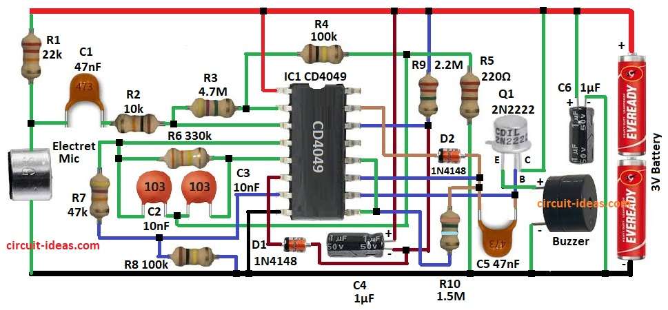
Main part of this circuit is CMOS IC CD 4049.
Mic catch sound and make small signal.
R1, R2, C1 fix signal and go to Schmitt trigger gate U1a.
R3 keep signal steady.
U1a and U1b make signal big and change to square wave.
C2 and C3 10nF and R6 filter noise make output stable.
R7 and R8 fix signal before D1 diode.
From U1c to D2 to Q1 2N2222 controls the buzzer.
C6 store power and make beep sound longer.
R9 and R10 control sensitivity and beep on time.
The circuit runs on 3V battery.
C4 and C5 cut noise from power.
Formulas with Calculations:
IC stage cutoff frequency:
fc = 1 / (2 × π × R1 × C1)
where,
- R1 is 22k
- C1 is 47nF
- fc is 154 Hz
154Hz which is low frequency limit of mic.
Beep time constant:
τ = R9 × C6
where,
- R9 is 2.2M
- C6 is 1µF
- τ is 2.2 sec
2.2 sec is when buzzer stays ON after whistle.
How to Build:
To build a Sound-to-Beep Circuit using IC CD 4049 follow the below mentioned steps for connections and assembling:
- Gather all parts.
- Connect pin 2 of U1a to pin 3 of U1a through R3.
- Connect R4 from pin 2 of U1a to the joint of R5, C2 and C3.
- Connect R2 and C1 in series from pin 3 of U1a to the joint of R1 and mic.
- Connect pin 4 of U1b to pin 5 of U1b through R6.
- Connect C2 and C3 in parallel between pin 4 and pin 5.
- Connect R7 between pin 4 of U1b and pin 7 of U1c.
- Connect R8 between the junction of R7 and pin 7 of U1c and GND.
- Connect cathode of D1 to pin 6 of U1c and anode of D1 to negative of C4 and connect positive of C4 to +3V battery.
- Connect pin 8 of U1c to GND.
- Connect R9 between pin 14 of U1d and negative of C4.
- Connect pin 15 of U1d to cathode of D2 and connect anode of D2 to one end of C5.
- Connect R10 from pin 11 of U1e to the junction of pin 12 of U1e and pin 9 of U1f.
- Connect pin 10 of U1f to base of Q1 through C5.
- Connect collector of Q1 to +3V battery and emitter of Q1 go to one end of buzzer and connect other end of buzzer to GND.
- Connect positive of C6 to +3V battery and negative of C6 to GND.
Conclusion:
Sound-to-Beep Circuit using IC CD4049 hears whistle and makes beep.
Schmitt trigger removes background noise.
Circuit is cheap, simple and is good for sound-based alerts.
Leave a Reply