Many people think multimeter can test any electric part, but this is not always safe especially for semiconductor.
Here, the article for Tester Probe Circuit show how to make one easy and safe tester only for semiconductor and this tester is easy to build as it uses small current which is good to test many type of semiconductor.
What is a Tester Probe Circuit:
The tester probe circuit is small tool for checking and testing; which helps to know how fast is electric circuit is working or not.
Also, it uses to check if electric parts and device are working good or not.
Circuit Working:
Parts List:
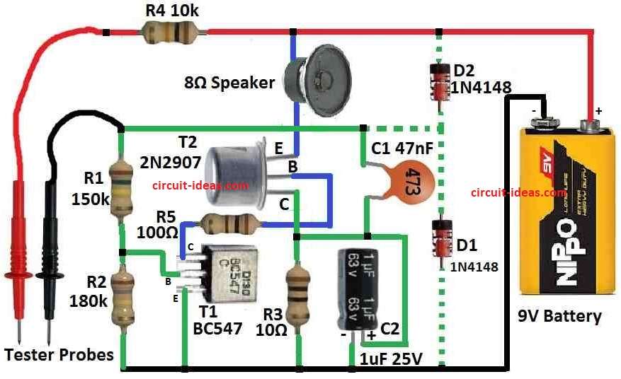
| Components | Values | Quantity |
|---|---|---|
| Resistors | 150k CFR 1/4 W | 1 |
| 180k CFR 1/4 W | 1 | |
| 10Ω CFR 1/4 W | 1 | |
| 10k CFR 1/4 W | 1 | |
| 100Ω CFR 1/4 W | 1 | |
| Capacitors | Ceramic 47nF | 1 |
| Electrolytic 1µF 25V | 1 | |
| Semiconductors | Transistors BC547 | 1 |
| Transistors 2N2907 | 1 | |
| Diodes 1N4148 (optional) | 2 | |
| Speaker 8Ω | 1 | |
| Battery 9V | 1 | |
| Tester probes red | 1 | |
| Tester probes black | 1 |
To begin with, T1 and T2 make a low-frequency LF oscillator controlled by voltage and the speaker acts as the load in this oscillator.
Here, the oscillator frequency depend on C1, R1, R4 and outside resistance between test wires, also R3 is collector resistor for T2 and C2 which give low frequency filter for this resistor.
How Oscillator Works:
Frequency of oscillator can change for testing and thee is no need to watch tester always because speaker give sound when testing.
Safety Features:
This circuit is safe for part we test; and diodes D1 and D2 protect tester parts from bad circuit.
Power Saving:
To test wires do not touch anything because circuit uses very small current and battery last long almost same as shelf life of battery.
Formulas:
The frequency (f) of oscillator and time for charging/discharging have same relation:
f = 1 / (Tcharge + Tdischarge)
where:
- Tcharge is the time to charge capacitor which depend on resistor R and capacitor C.
- Tdischarge is the time to discharge capacitor and also depend on R and C.
Tool Checking:
We can study the circuit to know which parts changes the frequency and how much it can go up or down.
Charging Time:
When voltage on capacitor C goes low one BJT turns ON and let capacitor charge; also the charging follow path through some resistors.
As a result, how fast it charge depend on current and resistance value.
Discharging Time:
When capacitor voltage reaches one level BJT changes state and turn OFF and then capacitor discharges through another path with different resistors.
Discharge speed also change with resistance in that path.
How to Build:
To build a Tester Probe Circuit follow the below mentioned connections steps:
- First, T1 and T2 must connect same way as told.
- Then circuit need resistors R1, R3 and R4.
- After that, capacitors C1 and C2 must be there for filter and control the frequency.
- Now add diodes D1 and D2 to protect from damage.
- Also, speaker should connect as load in oscillator part and for correct testing measurement, wires must connect properly.
How to test:
Below mentioned are the few methods for testing the Tester Probe Circuit:
Power ON:
- First, before use put battery in circuit the right way.
Connect Measuring Leads:
- After that, connect test wires to correct place in the circuit.
- Also, be sure test wires are not touching each other before testing IC or semiconductor.
Find Test Points:
- Then choose where we want to test on IC or semiconductor.
- Check datasheet to know good test points.
Touch Test Points:
- Also, use test wires to softly touch chosen points on IC or part.
- Now speaker should make sound if circuit is working.
Listen for Sound:
- Hear if sound from speaker change tone or volume, this change helps know what condition the semiconductor is in.
Disconnect and Try Again:
- Also, after testing one place remove the test wires and then test other points the same way.
Check Results:
- Look at sound result and compare with what IC or part should do and be sure signal should match the expected behavior.
Turn Off:
- Finally, after finish turn OFF the tester to save battery.
Conclusion:
Overall, this homemade Tester Probe Circuit gives safe and clear way to test semiconductor without breaking anything.
Also, follow the safety rules while working with electronics.