In many electronics low voltage is not enough but need only higher voltage.
Voltage booster circuit helps, take low voltage and makes it higher.
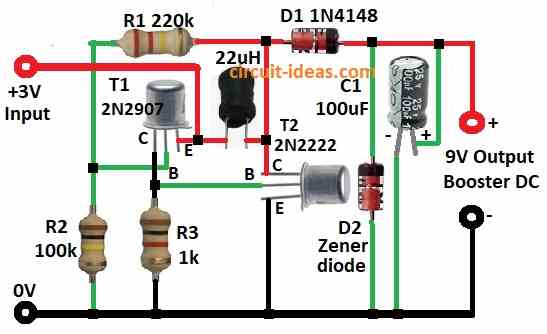
This project for Simple Transistor-Based Voltage Booster Circuit show how to make voltage booster using simple parts like:
PNP transistor 2N2907, NPN transistor 2N2222, resistors, capacitor, diode, inductor.
It takes 3V from battery and boost to higher voltage.
It is good for powering many devices.
Inductor 220µH store energy when switching.
Diode 1N4148 help give correct output voltage.
Zener diode 9V keep voltage stable and stop overvoltage.
Resistors 220k, 100k, 1k set transistor work properly.
This circuit teaches about switching, energy store in coil and voltage control.
It also show how small cheap parts can work in real life projects.
We want to help electronics learners and experts with this simple voltage booster example.
Circuit Working:
Parts List:
| Component Type | Specification | Quantity |
|---|---|---|
| Resistors | 220k 1/4 watt | 1 |
| 100k 1/4 watt | 1 | |
| 1k 1/4 watt | 1 | |
| Capacitor | Electrolytic 100µF 25V | 1 |
| Semiconductors | Transistor PNP 2N2907 | 1 |
| Transistor NPN 2N2222 | 1 | |
| Inductor 220µH | 1 | |
| Diode 1N4148 | 1 | |
| Zener Diode 9V | 1 | |
| Battery 3V | 1 |
This circuit take 3V DC and boost to 9V DC using inductor and transistor.
Inductor and collector of second transistor T2 connect to base of first transistor T1.
Collector of T1 connect to T2 and this design make whole circuit work.
Output capacitor C1 100µF remove noise from booster output.
Diode D1 handle high voltage spikes from inductor.
Zener diode keep output voltage steady.
Before Zener better to add one more filter capacitor to smooth DC signal.
When power ON then current goes through inductor and store energy slowly.
Then energy reaches T1 base and turn it ON and T1 full charges.
This also turns ON T2.
Both transistors ON release stored energy fast.
Then inductor has no energy and transistors turns OFF.
Cycle start again and inductor charge, discharge and repeat.
Diode D1 help change fast voltage spikes into stable high DC voltage.
Formulas:
To understand how this booster circuit works some important formulas are used.
1. Voltage Gain (Vout/Vin):
Vout = Vin × (R1 + R2) / R2
where:
- Vin is 3V for input voltage
- R1 is the 220k resistor
- R2 is the 100k resistor
2. Inductor Voltage (VL):
VL = L × (di / dt)
where:
3. Zener Regulation:
VZ = 9V
Zener diode keep output voltage around 9V.
4. Capacitor Charging:
VC = Vout × (1 − e^(-t / RC))
where:
- VC is the voltage across capacitor
- R is the load resistance
- C is the 100µF capacitor
- t is the time
5. Switching Frequency:
f = 1 / T
where:
- T is the time for one full inductor charge and discharge cycle
These formulas help to understand how voltage increases, how energy move and how output stay stable in this simple booster circuit.
How to Build:
To build a Simple Transistor-Based Voltage Booster Circuit following are the steps to follow for connections:
- Connect collector of transistor T1 2N2907 to GND through R3 1k resistor.
- Connect base of T1 between R1 100k and R2 220k junction.
- Connect emitter of T1 and one side of 22µH inductor to +3V input.
- Connect collector of T2 2N2222 to other end of 22µH inductor and also to R2 220k and anode of D1 1N4148.
- Connect base of T2 to collector of T1 and to R3 1k.
- Connect emitter of T2 to GND.
- Connect cathode of Zener diode D2 9V to cathode of D1 and anode of D2 to GND.
- Connect positive leg of C1 100µF to 9V output and negative leg to GND.
Conclusion:
This Simple Transistor-Based Voltage Booster Circuit uses transistors and inductor to convert 3V DC to 9V DC.
It works by charging and discharging inductor fast using feedback from both transistors.
This makes high voltage spikes which become steady 9V output with help of diodes and capacitor.
It is a good and simple way to increase voltage in small electronics and by showing how each part like diode and capacitor helps keep power stable.