The 555 IC is used in this TV Remote Signal Jammer Circuit because it generates fake IR signals similar to a remote, as a result, the TV becomes confused.
Furthermore, TV can not get the real remote signal, so we can watch the show without anyone changing the channel.
Also, parts used to complete this circuit are IR LED, ceramic capacitor, NPN transistor, potentiometer, resistors and 9V battery.
Circuit Working:
Parts List:
| Components | Values | Quantity |
|---|---|---|
| Resistors (All resistors are 1/4 watt unless specified) | 1k | 1 |
| 10k | 1 | |
| 220Ω | 1 | |
| 10Ω 1W | 1 | |
| Potentiometer 100k | 1 | |
| Capacitors | Ceramic 10nF | 1 |
| Semiconductors | IC 555 | 1 |
| Transistor BC547 | 1 | |
| IR Transmitter LED 5mm | 1 | |
| 9V Battery | 1 |
To begin with, 555 IC work as astable multivibrator in circuit and it makes square wave signals non-stop and also VR1 can change frequency from 32 to 40 kHz.
Most TVs use 38 kHz for remote signals.
Square wave goes to Q1 transistor and Q1 act like switch and turn IR LED ON/OFF with same frequency and IR LED make fake remote signals like real one.
Hence, the TV becomes confused and cannot detect the real remote signal.
So use VR1 to match jammer signal to 38 kHz and when jammer is ON TV does not work with remote.
Formulas:
To build a TV remote jammer, we need a continuous wave signal at a fixed frequency.
The 555 IC, when used as an astable multivibrator, generates this signal, therefore, use the following formula to set the frequency:
f = 1.44 / (R1 + 2 * R2) * C1
where,
- f is the frequency in Hz
- R1, R2 are the resistors in ohms Ω
- C1 is the capacitor in farads F
This formula helps design 555 timer to make right signal for jamming TV remote and we can adjust R1, R2 and C1 to get near 38 kHz.
How to Build:
To build a TV Remote Signal Jammer Circuit follow the below mentioned steps for connections:
Circuit Parts & Connections:
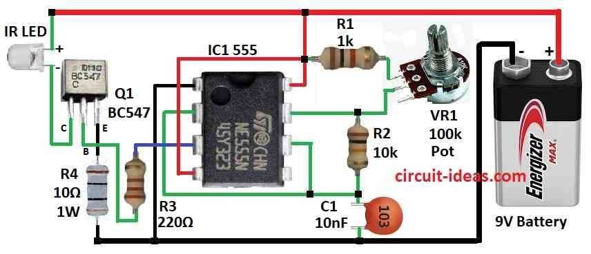
- First, use IC 555, transistor Q1, IR LED, R1, R2, R3, R4 resistors, VR1 potentiometer, C1 capacitor and 9V battery.
- Next, pin 1 of IC connects to ground
- After that, pin 2 connects to pin 6 and C1 then connect from pin 2 & pin 6
- Now pin 3 connects to Q1 base through R3
- Pin 4 and pin 8 connects to +9V
- R2 connects between pin 6 and pin 7 and pin 7 also connects to middle leg of VR1
- Top leg of VR1 connects to pin 4 & pin 8 through R1
- Q1 collector connects to +9V through IR LED, Q1 base connects to pin 3 through R3 and Q1 emitter connects to ground through R4
Important Notes:
- This circuit is for learning purpose only.
- Different TVs use different IR frequencies and we may need to adjust VR1 to match our TV which is usually 38 kHz.
- Put IR LED close to TV and point straight at it.
Conclusion:
Overall, this TV Remote Signal Jammer Circuit generates fake IR signals, so the TV becomes confused and ignores the real remote.
Hence, this circuit is only for study project, so do not use to disturb others.
Playing with these devices may be illegal in some places, so always use electronics for good purpose.
Leave a Reply