Wireless power is not new idea, but long time ago even Nikola Tesla tried this!
Now, many things like phone, toothbrush and some medical stuff charge without wire, but still we can make it better.
In this post, we will show how to make a easy Simple Wireless Power Transmission Circuit with transmitter and receiver using simple parts, so it will help us understand how wireless charging work.
What is a Wireless Power Transmission Circuit:
Wireless power circuit is small electric design which send power without wire and it uses something like magnetic field so move power at short or long distance.
Also, many wireless power devices use a common method called inductive coupling.
Transmitter Circuit Working:
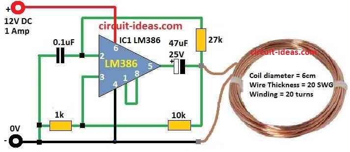
Parts List:
| Components | Values | Quantity |
|---|---|---|
| Resistors | 1k 1/4 W | 1 |
| 10k 1/4 W | 1 | |
| 27k 1/4 W | 1 | |
| Capacitors | Ceramic 0.1µF | 1 |
| Electrolytic 47µF 25V | 1 | |
| Semiconductors | IC LM386 | 1 |
| Coil As given in Diagram | 1 |
To begin with, this IC LM386 gives 1kHz square pulse signal at output and then this signal goes to copper coil and so start magnetic field moving at 1kHz.
Further, when coil magnetic field starts turning it makes strong changing magnetic field around it.
Receiver Circuit Working:
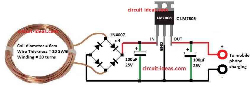
Parts List:
| Components | Values | Quantity |
|---|---|---|
| Capacitors | Electrolytic 100µF 25V | 2 |
| Semiconductors | Diode 1N4007 | 4 |
| IC 7805 | 1 | |
| Coil As given in diagram | 1 |
Here, receiver coil get EMF (electric force) when magnetic flux increases and also how big it is depends on coil turns and distance between coils.
Bridge rectifier first change AC to DC and then it fix the voltage from receiver coil and after that 7805 voltage regulator give steady DC voltage which is not too high or low.
Furthermore, we can change output frequency by adjusting timing resistor R1 and timing capacitor C1, also by changing coils on both the sides the circuit can match power needs better.
Formulas:
We used below formulas to find the frequency of RC oscillator:
f = 1 / (2 × π × R1 × C1)
where:
- f is output frequency in Hz.
- π (pi) is about 3.14.
- R1 is resistor value in ohms.
- C1 is capacitor value in farads
How the formula works:
R1 and C1 connect to make feedback loop and this loop makes voltage go up and down again and again, so this creates oscillation.
Frequency depends on R1 and C1.
Bigger values = slower frequency and Smaller = faster.
Induced EMF Formula:
Induced EMF ∝ Number of Windings × (1 / Distance between Coils)
(∝ means “proportional to”)
What it means:
EMF (ε) is voltage that we get when magnetic field changes and this happens in coil when nearby coil makes magnetic field go up and down.
More coil turns = more EMF.
Less distance between coils = stronger EMF.
Parts explained:
Induced EMF (ε): Voltage made in wire by changing magnetic field.
Number of Windings (N): How many turns of wire is in coil.
Distance between Coils (d): Space between main and second coil.
Smaller gap = better power transfer.
How this works:
In transformer or wireless coil, firstly current in first coil makes magnetic field and then if field keeps changing, it cuts second coil and so makes EMF which is voltage.
And this is how wireless power works using magnetic field
How to Build:
To build a Simple Wireless Power Transmission Circuit follow the below mentioned steps:
- First, use IC LM386 to make square wave oscillator.
- Next, to change output frequency connect timing capacitor C1 and resistor R1.
- Then give power to LM386 which is between 5V to 12V to start it.
- After that, LM386 sends 1kHz square signal to the coil.
- Also, at 1kHz coil start vibrating and make strong magnetic field that changes fast.
- Connect bridge rectifier and 7805 voltage regulator to the receiver coil.
- When both coils transmitter and receiver are close, magnetic flow happen.
- Also, the number of coil turns and the distance between coils show the EMF (voltage).
- Then bridge rectifier change AC to DC and 7805 make voltage stable and safe.
Conclusion:
To conclude, this Simple Wireless Power Transmission Circuit is simple project which helps us to learn how wireless power works, so it is good for beginners and also we can try more experiments to improve it.