Theremin is one very old electronic music instrument.
It make strange space type sound without touching any part.
Human hand move near antenna or plate and the pitch of sound changes.
This happen because hand change the capacitance value near the circuit.
In this article we will show very small and Single Transistor Theremin Oscillator Circuit using few parts.
Circuit Working:
Parts List:
| Part Name | Value | Quantity |
|---|---|---|
| Resistor | 270k 1/4 watt | 1 |
| Capacitors | Ceramic 0.1µF, 471pF | 1 each |
| Semiconductors | Transistor 2N2907 | 1 |
| Air core or ferrite slug type (see the text below) | 1 | |
| Metal plate or aluminum, brass, or even copper sheet | 1 |
This circuit uses NPN transistor 2N2907.
It work as RF oscillator.
The metal plate is about 20 to 30 cm square in square and is where hand comes close.
When hand is near then capacitance change and frequency also change.
Coil and capacitor make tank circuit for oscillation.
The transistor give energy to oscillation so it does not stop.
The sound frequency later goes to amplifier or mixer stage to hear.
The 270k resistor give bias to transistor.
The 0.1uF capacitor give feedback.
The coil and 500pF capacitor set main frequency.
Plate is kept near radio tuned to strong 900 kHz station.
Adjust coil slug for best tone.
Move hand near the plate and pitch will change.
Coil Making:
RF tank coil air core or ferrite slug type
Inductance L is typically 5µH to 12µH
Wire is enamelled copper wire
Gauge is AWG 28 to 32 (0.3 to 0.4 mm) is common
Turns is about 40 to 60 turns depends on coil form diameter
Coil Form is plastic, phenolic tube and diameter from 8 to 12 mm
Length of winding is about equal to coil diameter for stable inductance
Formulas:
For LC oscillator frequency formula:
f = 1 / (2 * pi * sqrt(L * C))
where,
- f is frequency in Hertz
- L is inductance in Henry
- C is capacitance in Farad.
When hand come close the capacitance increase and so frequency decrease.
This change make sound pitch difference when mixed with another fixed oscillator.
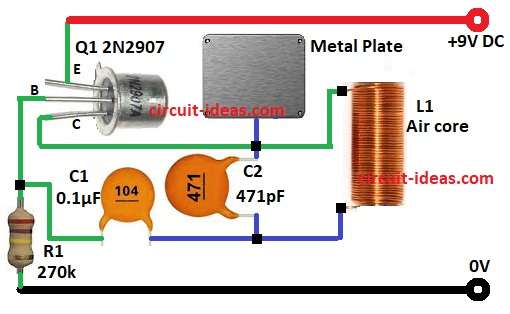
How to build:
To build a Single Transistor Theremin Oscillator Circuit follow the below steps for connections:
- Gather all the parts as shown in circuit diagram
- Connect emitter pin of transistor Q1 to +9V DC
- Connect base pin of transistor Q1 to GND through resistor R1
- Connect collector pin of Q1 transistor to one end of capacitor C2 and one end of Coil
- And other end of Coil connect to GND
- Connect capacitor C1 to one end of resistor R1 and other end to capacitor C2
- Connect the metal plate between the collector and one end of coil
Conclusion:
This is simple Single Transistor Theremin Oscillator Circuit
By moving hand near pitch plate the frequency of oscillator change because capacitance change.
With audio mixer or beat frequency stage it give the classic Theremin sound.
It is good small project to understand how capacitance and oscillators can make music.
Leave a Reply