Now days mobile phones are very important part of our life, but charging it always need electricity.
If we are outside or village side where there is no power then problem comes; so this small Solar Powered Mobile Charger Circuit can give 4.7V output from 9V solar panel.
Also, it is simple and with low cost circuit for emergency charging.
Circuit Working:
Parts List:
| Components | Values | Quantity |
|---|---|---|
| Resistors | 1k 1/4 watt | 1 |
| 560Ω 1/4 watt | 1 | |
| Capacitors | Electrolytic 100µF 25V | 2 |
| Semiconductors | Transistor TIP122 | 1 |
| Green LED | 1 | |
| Zener Diode 5.7V | 1 | |
| Diode 1N4007 | 1 | |
| Solar Panel 9V 5 watt | 1 | |
| Mobile ‘C’ type connector | 1 |
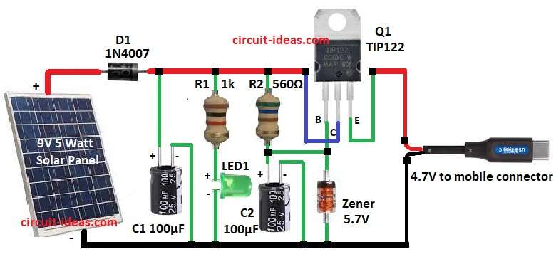
The solar panel provides a 9V DC supply when sunlight falls on it, then the 1N4007 diode blocks reverse current from flowing from the battery back to the solar panel during the night.
Capacitor C1 works as filter and smooth the supply, resistor R1 and LED1 is just for indicator to show circuit is working and then resistor R2 control base current of transistor Q1.
The 5.7V Zener diode is the main component of the circuit because it regulates the output voltage, capacitor C2 improves stability and removes ripples from the output.
At output side we get around 4.7V which is suitable for charging mobile phone.
Formulas:
The following formulas explain the Solar Powered Mobile Charger Circuit:
Base current through R2 560Ω into TIP122 transistor.
TIP122 Vbe (Darlington) = 1.2V (two junctions)
Zener Vz = 5.7V
Voltage across R2: VR2 = Vin − Vbe − Vz = 9 − 1.2 − 5.7 = 2.1V
Base current Ib = VR2 / R2 = 2.1 / 560 = 0.00375 A = 3.75 mA
Power in R2: PR2 = VR2 × Ib = 2.1 × 0.00375 = 0.0079 W which is safe.
How to Build:
To build a Solar Powered Mobile Charger Circuit follow the below mentioned steps:
- First, gather all the parts as shown in circuit diagram.
- Next, connect solar panel 9V positive to diode D1 anode and negative of panel go to ground.
- Then cathode of D1 connect to capacitor C1 positive and same point connect to resistor R1 and R2.
- Now other end of R1 connect to LED1 anode and LED1 cathode go to ground and other end of R2 connect to base pin of transistor Q1.
- After that, collector pin of Q1 connect back to solar panel positive and diode D1 cathode point and emitter pin of Q1 give output 4.7V to mobile connector.
- Also, Zener diode anode and capacitor C2 negative go to ground.
- Finally, mobile charging connector take positive from emitter of Q1 and negative from ground.
Note:
- Also, if required we can upgrade Zener power rating and maybe add protection resistor or heatsink transistor otherwise it might damage.
Conclusion:
To conclude, this Solar Powered Mobile Charger Circuit uses a 9V solar panel and provides about 5.7V regulated output through a Zener diode; the circuit is simple, low-cost and useful for charging mobile devices with solar energy.
Furthermore, it is useful for charging small mobile phones when there is no electricity and also this circuit is good for learning and small emergency use.