First of all, this Solar Powered Animal Scarer Circuit is very simple and very useful project for farm, garden and home protection.
To begin with, it use solar energy, so it save electricity and work in eco-friendly way.
Moreover, it scare animals like cat, dog, monkey and birds by using flashing light or sound signals.
In addition, it works automatically, so no need to always switch ON or OFF; overall, it is cheap, smart and easy circuit for beginner electronics projects.
Circuit Working of Animal Repellent :
Parts List:
| Components | Values | Quantity |
|---|---|---|
| Resistors | 100Ω 1/4 watt | 3 |
| 1M 1/4 watt | 1 | |
| Potentiometer 100k | 2 | |
| Capacitors | Ceramic 0.22µF | 1 |
| Semiconductors | IC 4060 | 1 |
| LDR | 1 | |
| LEDs 5mm 20mA | 9 |
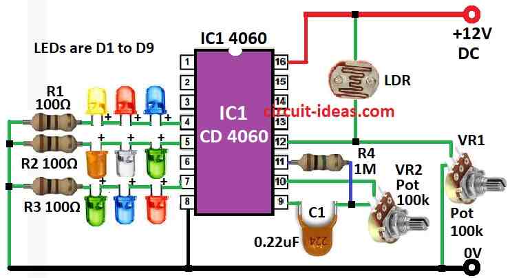
To begin with, this solar circuit scare night animals like bat, cat from farm, garden and it make bright flash red, blue, white LED.
Also, it works auto with ON at night and OFF at day and LDR with IC CD 4060 control flashing.
Here, VR1 set light sense and VR2 set flash speed, also the circuit uses 12V battery or supply.
Formulas:
We can use IC 4060 to make animal repeller circuit.
Use this formula to find frequency (approx):
f = 1.44 / ((R + 2 × Rpot) × C)
where,
- Rpot is variable resistor we can turn to change frequency.
To stop LED burning use resistor:
RLED = (Vsupply – VLED) / ILED
where,
- Vsupply is the battery power
- VLED is LED voltage for 2V
- ILED is LED current from 10 to 20 mA
How to Build:
To build a Solar Powered Animal Scarer Circuit one needs to follow the below mentioned steps:
- First, gather all the parts as per the circuit diagram, while the LDR goes to pin 12 of IC 4060 for reset control by light.
- Also, VR1 with the LDR set the sensitivity, while VR2 set the LED flashing speed.
- Now, R1, R2, and VR2 limit the LED current.
- Then, use 1N4007 diode with the solar panel and battery to stop reverse power flow.
Connect LEDs like this:
- Red to pin 7
- Blue to pin 5
- White to pin 4
Circuit Working of Animal Scarer Solar Power Supply:
Parts List:
| Components | Values | Quantity |
|---|---|---|
| Resistors | R1 10Ω 1 watt | 1 |
| R2 1k 1/4 watt | 1 | |
| Capacitors | Electrolytic 2200µF 12V | 1 |
| Semiconductors | Diodes 1N4007 | 2 |
| LED any 5mm 20mA | 1 | |
| Solar Panel 18V | 1 | |
| Battery 12V | 1 |
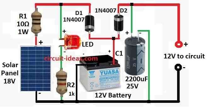
This circuit take power from solar battery and in daytime the sun charge battery through R1 and D1, while green LED show charging status.
Also, at night D1 stop working and D2 give battery power to circuit, while R1 limit the current and big capacitor C1 keep the power smooth and stable.
How to Build:
Below mentioned are the steps to build a Animal Scarer Solar Power Supply Circuit:
- First, solar positive goes to battery positive while solar negative goes to D1 anode.
- Then, D1 cathode connects to battery positive and LED anode, while LED cathode goes to battery negative.
- Next, D2 cathode connects to battery negative and D2 anode goes to circuit positive.
- After that, one side of R1 goes to solar positive while the other side connects to D1 anode.
- Now, C1 positive connects to D1 anode and C1 negative goes to battery negative.
Conclusion:
In conclusion, this Solar Powered Animal Scarer Circuit using IC 4060 is a simple and useful project for protecting farm, garden and home area from unwanted animals.
Moreover, the IC 4060 control the flashing and timing operation, while the solar panel and battery help the circuit work with low power cost.
Also, the circuit works automatically in night time, therefore it save energy and need less manual control.
Finally, this project is low-cost, easy to build and good for beginners who want to learn solar and protection circuits.
Leave a Reply