Transformerless 12V Switching Power Supply Circuit is small, smart and with no big transformer; it changes high AC to steady low DC using fast switch.
Circuit is lightweight, good for low power, embedded, IoT and for industrial control and also this circuit requires 12V 120mA output and works with 85 to 230V AC and uses LNK304 IC.
LNK304 is a simple, efficient switcher which works in buck, buck-boost and flyback and it has auto start, protect from short circuit and open loop; furthermore, it usually is SMD but we need to be careful while soldering.
Circuit Working:
Parts List:
| Components | Values | Quantity |
|---|---|---|
| Resistors (All resistors are 1/4 watt unless specified) | 8.2Ω 2W | 1 |
| 2.05k | 1 | |
| 13k | 1 | |
| 3.3k | 1 | |
| Capacitors | Ceramic 100nF | 1 |
| PPC 4.7µF 400V | 2 | |
| Electrolytic 10µF 25V | 1 | |
| Electrolytic 100µF 25V | 1 | |
| Semiconductors | IC LNK304 | 1 |
| Diode 1N4007 | 2 | |
| Diode UF4005 | 1 | |
| Diode 1N4005GP | 1 | |
| Inductor coil 1mH | 1 | |
| Inductor coil 1mH 280mA | 1 |
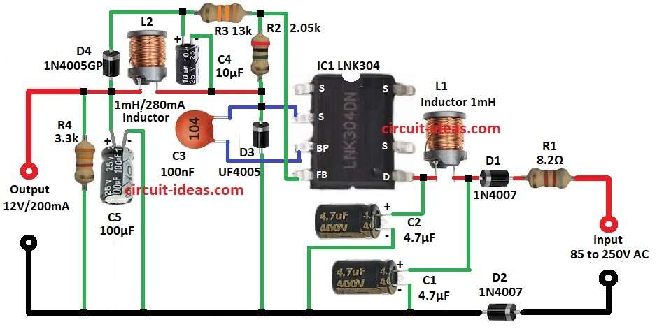
Circuit works like SMPS using LNK304 chip and this chip has high voltage MOSFET which control for efficient power change.
Further, it takes 85 to 250V AC gets rectified and filtered with smooth DC.
Then R1 is a fuse resistor which melts if overheat, D1 and D2 are bridge rectifier which makes AC to pulsating DC and C1 and C2 is a input filter with smooth DC.
After that, L1 is with cut high-frequency noise and L2 is choke with steady output and with less ripple.
In addition, LNK304 is efficient power conversion, C3 keep chip stable, R2 and R3 sets 12V output and C4 smooth switching output.
Also, D3 is fix with high-frequency AC from switch, C5 finals the smooth, R4 is the load resistor and D4 gives correct polarity and safety.
At last the circuit gives 12V DC 200mA which is good for small DC devices.
Formulas with Calculations:
Input Power:
P_out = 12V × 0.2A = 2.4W
Efficiency = 75%
P_in = P_out / Efficiency = 2.4 / 0.75 = 3.2W
R1 Current:
R1 = 8.2Ω, V_in = 230V
I = 230 / 8.2 = 28A
This is surge only but actual circuit operation is less
Inductor Ripple (L1):
L1 = 1mH, f = 65kHz, D = 0.5, V_out = 12V
ΔI_L = (12 × 0.5) / (65,000 × 0.001) = 6 / 65 = 92mA
Output Capacitor Ripple (C5):
C5 = 100µF, I_load = 0.2A, f = 65kHz
V_ripple = 0.2 / (65,000 × 0.0001) = 0.2 / 6.5 = 30mV
How to Build:
To build a Transformerless 12V Switching Power Supply Circuit follow the below mentioned steps for connections and assembling:
- First, assemble all parts as per circuit diagram.
- Next, connect S pin of IC1 LNK304 to 12V output supply and then connect capacitor C3 between BP pin and S pin of IC1.
- Then connect resistors R2 and R3 in series between S pin of IC1 and the junction of capacitor C4 and cathode of diode D4.
- After that, connect cathode of diode D3 to S pin of IC1 and anode of diode D1 to GND.
- Also, connect positive terminal of capacitor C5 to S pin and negative terminal of C5 to GND and then connect inductor L2 between capacitor C4 and capacitor C5.
- Now connect resistor R4 from S pin of IC1 to GND.
- Further, connect D drain pin of IC1 to AC input supply 85V to 250V.
- Then connect positive terminal of capacitor C2 to D pin and negative terminal of C2 to GND.
- Inductor L1 connect between capacitor C1 and capacitor C2, then connect positive terminal of capacitor C1 to D pin and negative terminal of C1 to GND.
- Finally, connect one end of resistor R1 to AC input supply and the other end to anode of diode D1 and then connect cathode of diode D2 to the other AC input supply.
Conclusion:
To conclude, this Transformerless 12V Switching Power Supply Circuit is small, cheap and efficient for 12V supply; also the circuit is good for LED, IoT, embedded.
Moreover, IC LNK304 makes safe, stable and efficient working circuit
Leave a Reply