Switching regulator is good to change power, as it control voltage by fast ON/OFF of power transistor and LM5007 IC is high voltage buck regulator and it lower voltage from big input voltage range.
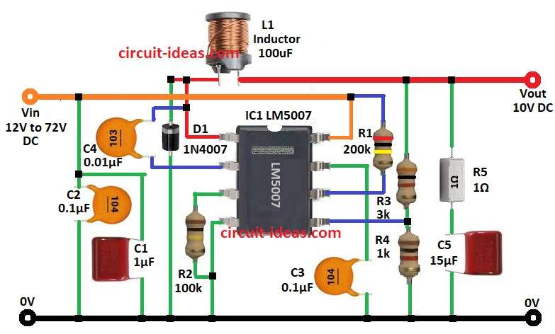
Also, this step-down regulator have all parts inside for good and cheap circuit; here, 10V Switching Power Supply Circuit with IC LM5007 gives steady 10V from 12V to 72V input.
Furthermore, it is good for industry and car use and IC LM5007 max output current is 700mA.
Circuit Working:
Parts List:
| Components | Values | Quantity |
|---|---|---|
| Resistors (All resistors are 1/4 watt unless specified) | ||
| R1 | 200k | 1 |
| R2 | 100k | 1 |
| R3 | 3k | 1 |
| R4 | 1k | 1 |
| R5 | 1Ω | 1 |
| Capacitors | ||
| C1 | PPC 1µF 100V | 1 |
| C2, C3 | Ceramic 0.1µF | 2 |
| C4 | Ceramic 0.01µF | 1 |
| C5 | PPC 15µF 100V | 1 |
| Semiconductors | ||
| IC | IC1 LM5007 | 1 |
| D1 | Diode 1N4007 | 1 |
| L1 | Inductor Coil 100µH | 1 |
LM5007 IC is buck converter and it takes high DC voltage and makes steady 10V output and before voltage goes to IC it passes through capacitors C1 and C2 for stability.
Then LM5007 IC works by fast ON/OFF of internal MOSFET and this sends energy to output through inductor L1.
After that, resistor R1 helps start circuit and resistor R2 controls how long circuit stays OFF, then capacitor C3 is decoupling and makes circuit work better.
Also, fast MOSFET switching moves energy well through L1 and then diode D1 protect circuit from voltage spikes.
Output voltage is steady by resistor divider R3 and R4 and capacitor C5 smooth output signal and then resistor R5 and capacitor C5 make filter and improve performance.
Formulas with Calculations:
Output voltage Vout calculation:
Vout = 1.225V × (1 + R3 / R4)
where,
- R3 is 3k
- R4 is 1k
So,
Vout = 1.225 × (1 + 3000/1000) = 1.225 × 4 = 10V
Inductor selection:
L = (Vin – Vout) × D / (fs × Iout)
where,
- Vin input voltage
- Vout is output voltage
- D is duty cycle
- fs is switching frequency
- Iout is output current
In practice use 100µH inductor.
Output capacitor selection:
C = Iout / (8 × fs × Vripple)
where,
- Iout is output current
- fs is switching frequency
- Vripple allowed voltage ripple
So use 15µF capacitor C5 to keep ripple low.
How to Build
To build a 10V Switching Power Supply Circuit with IC LM5007 follow the below mentioned steps:
- First, connect pin 1 of IC1 to 10V output Vout, then diode D1 cathode connect to pin 1 of IC1 and diode D1 anode connect to ground GND.
- Next, connect inductor L1 from pin 1 of IC1 to junction of capacitor C4 and resistor R3.
- After that, one side of capacitor C4 connect pin 2 of IC1 and other side connect junction of diode D1 and L1 coil.
- Also, resistors R3, R4, R5 and capacitor C5 connect in parallel between junction of L1 coil and 10V output.
- Then connect pin 3 of IC1 to pin 4 of IC1 and then to GND through resistor R2.
- Further, pin 5 of IC1 connect between resistor R3 and R4.
- Now pin 6 connect to pin 8 of IC1 through resistor R1.
- Pin 7 connect to GND through capacitor C3 and pin 8 connect to input voltage from 12V to 72V.
- Finally, capacitors C1 and C2 connect in parallel to GND from junction of resistor R1 and input voltage.
Conclusion:
To conclude, this 10V Switching Power Supply Circuit with IC LM5007 lowers voltage from 12V to 72V input to steady 10V output.
Moreover, it works with low power loss and is good for industrial, automotive and embedded system power needs.
Leave a Reply