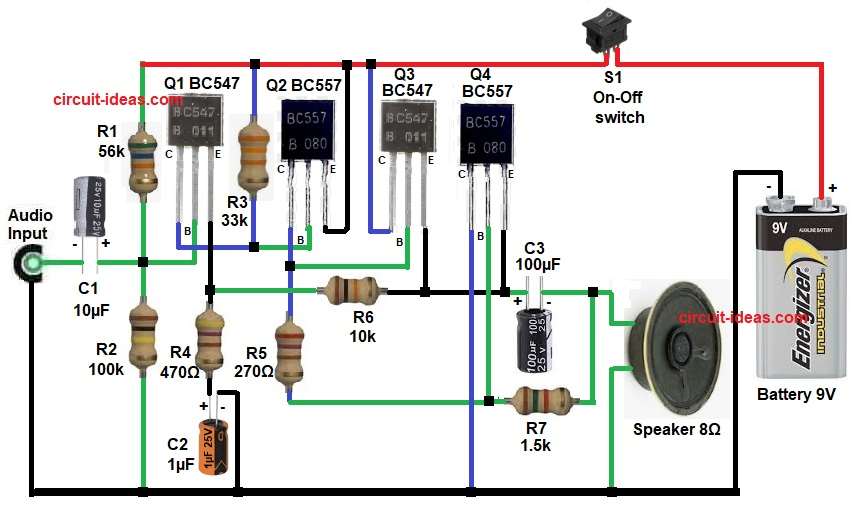
A Transistor Based Audio Amplifier Circuit is a simple and useful audio circuit that increases weak audio signals into a louder sound signal.
This circuit uses four transistors, namely two BC547 NPN transistors and two BC557 PNP transistors, because of its simple design, students and beginners can easily understand and build it.
Moreover, this circuit works from a 9V battery supply, so it is suitable for small speaker applications, mini audio projects and learning purposes.
The input audio signal can come from a mobile phone, microphone preamp or any low-level audio source and after amplification the circuit drives an 8 ohm speaker.
Circuit Working:
Parts List:
| Components | Values | Quantity |
|---|---|---|
| Resistors (All resistors are 1/4 watt) | 56k,100k, 100k, 470Ω, 270Ω, 10k, 1.5k | 1 each |
| Capacitors | Electrolytic 10µF 25V, 1µF 25V, 100µF 25V | 1 each |
| Semiconductors | Transistors BC547, BC557 | 2 each |
| Speaker 8Ω | 1 | |
| On-Off switch | 1 | |
| Battery 9V | 1 |
At first, the audio signal enters from the input terminal then capacitor C1 passes only the AC audio signal which blocks the DC part, so the circuit gets a clean input signal.
Next, transistor Q1 BC547 works as the first amplifier stage which amplifies the weak input signal and also resistors R1 and R2 give the required bias voltage to the base of Q1, because of this, Q1 works in the correct region.
After that, the amplified signal goes to transistor Q2 BC557, here Q2 increases the signal strength more and it also improves the voltage gain at the same time the resistor R3 gives proper biasing to Q2.
Then, the signal moves to Q3 and Q4 and these two transistors make the output driver stage, in this stage both transistors give enough current to drive the speaker and as a result the speaker produces louder sound.
Further, capacitor C3 sends the amplified AC signal to the speaker which also blocks DC voltage from reaching the speaker, so it protects the speaker from damage.
Meanwhile, resistor R7 works as a gain or volume control resistor and by changing this value we can adjust the output sound level.
S1 is power switch which starts the circuit, when switch is ON the circuit works and when switch is OFF the circuit stops and it also saves battery.
Finally, the complete circuit amplifies a small audio signal into clear audible sound output.
How to Build:
To build a Transistor Based Audio Amplifier Circuit follow the below connection steps:
- First, assemble all the components as shown in the circuit diagram above.
- Then connect the positive terminal of the 9V battery positive and then connect the negative terminal to the ground rail.
- Next, take transistor Q1 and connect its base to the junction of capacitor C1 positive and resistors R1 and R2.
- Connect the collector of Q1 to the base of transistor Q2 and resistor R3.
- Connect the emitter of Q1 between resistor R4 and resistor R6.
- After that, take transistor Q2 and connect the base of Q2 to the collector of Q1.
- Connect the collector of Q2 to the base of transistor Q3 and resistor R5.
- Then connect the emitter of Q2 to the positive supply.
- Next, take transistor Q3 and connect its base between the collector of Q2 and resistor R5.
- Connect the collector of Q3 to the positive supply.
- Connect the emitter of Q3 to the junction of resistor R6, positive terminal of capacitor C3 and emitter of transistor Q4.
- Finally, take transistor Q4 and connect its base between resistor R5 and resistor R6.
- Connect the collector of Q4 to the negative line of the 9V battery.
- Connect the emitter of Q4 to the same junction point of resistor R6, positive of capacitor C3 and emitter of transistor Q3.
- Next, take capacitor C1 and connect its positive side toward the base of transistor Q1 and connect the negative side to the audio input line and ground.
- Then connect the positive end of C2 to one end of resistor R4 and connect its negative end to the ground line.
- Last capacitor C3 positive side goes toward the transistor output an connect the other side to the speaker.
- Switch S1 is connected at positive rail to save the 9V battery and to start start the circuit and to stop the circuit.
- Finally, connect one end of the 8 ohm speaker to the output through capacitor C3 negative side and the other end to ground.
Conclusion:
This Transistor Based Audio Amplifier Circuit is simple and useful for audio signal amplification.
It uses easily available components like BC547 and BC557 transistors, so beginners can make it easily, also the 9V supply makes the circuit portable and easy for testing.
Overall, this circuit is very good for educational projects, practical learning and low power speaker use.
Therefore, it is a good basic audio amplifier project for students and electronics beginners.