Electricity failure is common in many areas, so we need backup light.
This Transistor Based Mini Emergency Light Circuit is simple and is with low cost.
It uses few components only and it works automatically when power fails.
Therefore, it is useful for homes and small offices and it is easy to build even for beginners.
This article explains full circuit working and construction in simple way.
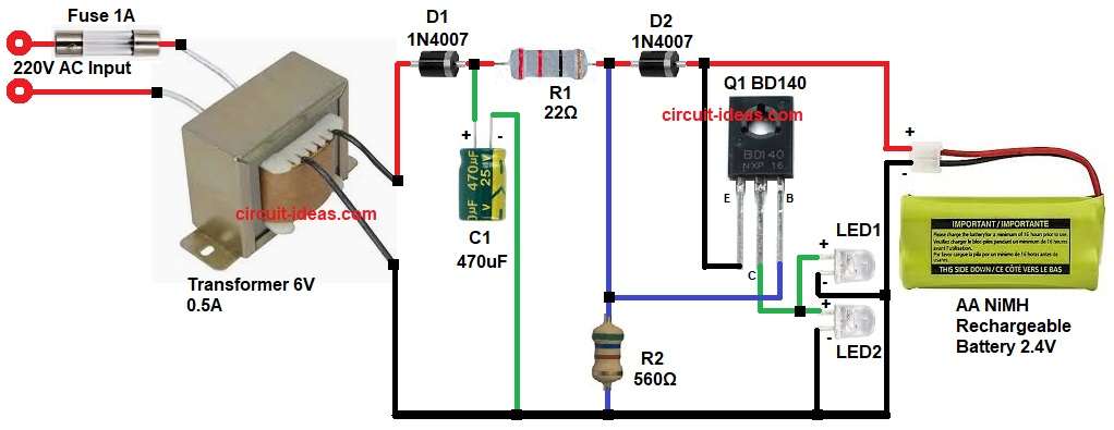
Circuit Working:
Parts List:
| Components | Value | Quantity |
|---|---|---|
| Resistors | 560Ω 1/4 watt, 22Ω 1 watt | 1 each |
| Capacitor | Electrolytic 470uF 25V | 1 |
| Semiconductors | Transistor BD140 PNP | 1 |
| Diode 1N4007 | 2 | |
| Transformer 220V to 6V 0.5A | 1 | |
| Fuse 1 Amp | 1 | |
| White LEDs 5mm | 2 | |
| 2.4V Rechargeable Battery Pack | 1 |
At first, when AC mains is present the transformer steps down 220V AC to 6V AC.
Then diode D1 rectifies AC to DC and after that capacitor C1 filters the ripple and gives smooth DC.
Now this DC charges the 2.4V battery through resistor R1 and diode D2.
At the same time the transistor Q1 remains OFF and therefore LEDs remain OFF during normal power supply.
However, when power fails the transformer output becomes zero and then the charging voltage disappears.
As a result, transistor BD140 becomes forward biased and so the battery supplies current to LEDs.
Therefore, LEDs glow automatically and thus the circuit works as automatic emergency light.
How to Build:
To build a Transistor Based Mini Emergency Light Circuit following are the steps one needs to follow:
- Start, first by collecting all the circuit parts as shown in circuit diagram.
- Then start with transistor Q1 emitter pin connects to positive battery terminal.
- Collector pin connects to LED1 and LED2 anode side.
- LED negative connects to ground.
- Base connects between one end of resistor R1 and R2.
- Battery negative connects to circuit ground.
- Diode D2 connects between rectified output and battery positive.
- Capacitor C1 positive connects between diode D1 cathode and resistor R1 one end.
- Capacitor negative connects to ground.
- Fuse connects in series with 220V AC input primary.
- Transformer secondary connects to D1 diode input.
Conclusion:
To conclude, this Transistor Based Mini Emergency Light Circuit is very useful during power failure.
It works automatically without manual switch and it charges battery during normal power.
It provides light when power goes OFF and therefore, it is reliable and economical solution.
Finally, anyone with basic electronics electronic knowledge can build this circuit successfully.
Leave a Reply