This Voice and Music Audio Mixer Circuit using IC LM3900 is a voice and music audio mixer.
It uses LM3900 quad op-amp.
It take many audio inputs like mic signal and line audio and mix to one output.
LM3900 IC is good choice as it give high gain and work with single power from +5V to 30V.
So circuit is useful for many things like sound system, public address and music instruments.
Each input have preset knob to adjust gain.
User can control volume easily.
It mix audio well and keep sound clean like, original.
Circuit Working:
Parts List:
| Component | Value | Quantity |
|---|---|---|
| Resistors (All resistors are 1/4 watt unless specified) | 1Ω | 2 |
| 1M | 4 | |
| 470Ω | 6 | |
| 330Ω | 2 | |
| Preset 1k | 4 | |
| Capacitors | Ceramic 0.1μF | 3 |
| Ceramic 0.47μF | 2 | |
| Semiconductors | IC LM3900 Quad Op-Amp | 1 |
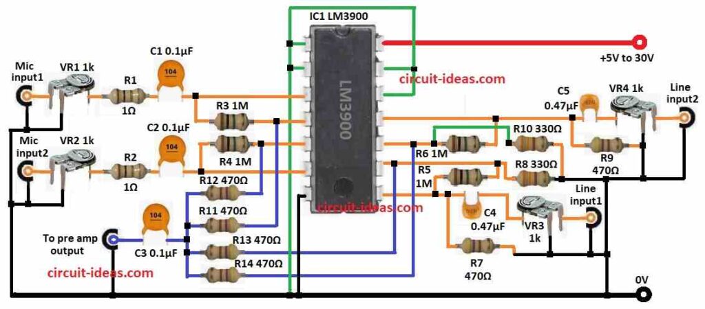
This circuit have 4 input channels 2 mic (Mic input1, Mic input2) and 2 line (Line input1, Line input2).
Each input goes through variable resistors VR1, VR2, VR3, VR4 which are all 1k).
These help control volume for each input.
To block DC and pass only audio there are coupling capacitors C1, C2, C3 from 0.1µF and 0.47µF at input.
LM3900 op-amp is used to amplify and mix signals.
Each channel uses one part of LM3900 in summing the setup.
Gain is set using feedback resistors R3, R4, R5, R6 all 1M and this boost signal for next stage.
All op-amp outputs goes to one point and mix together.
After mix, signal goes through capacitor C3 to remove DC offset.
Final signal can go to preamp or direct to audio amplifier.
Circuit works with single power from +5V to +30V with no need of negative voltage because of so easy design.
Good grounding is needed to stop the noise.
Current limit resistors R11, R12, R13, R14 of 470Ω keep op-amp output safe and steady.
Formulas with Calculations:
Formulas and Calculations for Voice & Music Mixer using LM3900:
Gain of each op-amp:
Gain = Feedback Resistor / Input Resistor
Example: Gain = R3 / R1 (for Mic input1)
Output voltage of mixer:
Vout = (V1 × Gain1) + (V2 × Gain2) + (V3 × Gain3) + (V4 × Gain4)
where,
- V1, V2, V3, V4 are the inputs from 4 channels
- Gain1–Gain4 are gain of each channel
Input impedance (Zin):
Zin = Input Resistor
R1 and R2 are input resistors
Cutoff frequency (Fc):
Fc = 1 / (2 × π × R × C)
where,
- R is the input resistor for R1, R2
- C is the capacitor for C1, C2
Example calculation:
R1 = 1Ω, C1 = 0.1μF
Fc = 1 / (2 × 3.1416 × 1 × 0.1 × 10⁻⁶)
Fc = 1.59 MHz
Total current used:
I = (Vcc – Vout) / R
where,
- Vcc is the supply voltage
- Vout is the output voltage
- R is the total resistance in circuit
How to Build:
To build a Voice and Music Audio Mixer Circuit using IC LM3900 follow the below steps for connections:
- Gather all parts from circuit diagram.
- Connect pin 1 of IC1 LM3900 to pins 2, 12, 13 and GND.
- Connect pin 3 to pin 4 with resistor R3.
- From pin 1 connect to one end of capacitor C1 and other end to resistor R1.
- Other end of R1 goes to center leg of VR1 preset and one leg to Mic input1, third leg to GND.
- Connect pin 4 to +5V to +30V power supply (positive).
- Connect pin 5 to pin 6 using resistor R4.
- Pin 6 goes to one end of capacitor C2 and other end to resistor R2 and other end of R2 connects to center of VR2 with one leg to Mic input2 and third leg to GND.
- Connect pin 7 to GND.
- Connect pin 8 to pin 9 with resistor R5.
- From pin 8 connect to one side of capacitor C4 and other side to center leg of VR3
- Connect one leg to Line input1 and third leg to GND.
- Also connect resistor R7 from pin 8 to GND.
- From pin 9 connect R8 to GND.
- Connect pin 10 to pin 11 with resistor R6.
- Connect R10 from pin 10 to GND.
- Pin 11 goes to one side of capacitor C5
- Connect other side to center of VR4 with one leg to Line input2 and third leg to GND.
- Also connect R9 from pin 11 to GND.
- Connect resistors R11, R12, R13, R14 from pins 4, 5, 9, 10 of LM3900.
- Capacitor C3 connect between R12 and R13 and this is preamp output.
Conclusion:
This Voice and Music Audio Mixer Circuit using IC LM3900 is low cost and smart way to mix different audio signals.
LM3900 give strong gain and work on wide voltage range which is so useful in many places like events, music or sound setups.
Each input has gain control with preset which is so easy to balance levels.
Coupling capacitors remove DC and keep audio clean.
Circuit design is simple with few parts and is easy to build and fix.
It is good for both hobby and professional audio use.
Leave a Reply