A stable power supply is the backbone of every electronic circuit and without proper voltage, even the best circuit cannot work correctly, however, transformer output is also not stable and it also contains ripple.
Therefore, this circuit uses voltage regulator ICs, the 7805 regulator normally gives fixed +5V output and similarly the 7905 regulator gives fixed −5V output.
However, resistors and potentiometers change the reference voltage and because of this the circuit allows adjustment of the output voltage.
So, the circuit can provide:
+5V to +25V
-5V to -25V
Because of this feature, the circuit is useful for op-amp circuits, audio amplifiers and laboratory experiments.
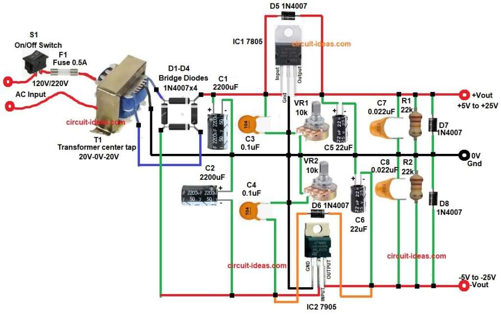
Circuit Working:
Parts List:
| Components | Values | Quantity |
|---|---|---|
| Resistors | 22k 1/4 watt | 2 |
| Potentiometer 10k | 2 | |
| Capacitors | Electrolytic 2200uF 50V, 22uF 25V | 2 each |
| Ceramic 0.1uF, 0.022uF | 2 each | |
| Voltage Regulator ICs 7805, 7905 | 1 each | |
| Bridge Rectifier Diodes 1N4007 1A 1000V | 4 | |
| Protection Diodes 1N4007 | 4 | |
| Transformer center tap secondary 20V-0V-20V, primary 120V/220V | 1 | |
| Fuse 0.5A | 1 | |
| On/Off Switch | 1 |
First, AC mains goes to the transformer and this transformer reduces the voltage to 20V-0-20V AC.
Next, the bridge rectifier changes AC into DC and bridge diodes D1-D4 do this rectification.
After that, capacitors C1 and C2 remove the ripple from the DC voltage and therefore, the circuit gets smoother DC voltage.
Then this DC voltage goes to the voltage regulators.
The IC 7805 gives regulated positive voltage and at the same time, the IC 7905 gives regulated negative voltage.
However, the circuit uses potentiometers VR1 and VR2 and these potentiometers change the reference voltage, because of this, the output voltage becomes adjustable.
Capacitors C3 and C4 increase circuit stability and similarly, capacitors C5, C6, C7 and C8 reduce noise and ripple in the output.
Additionally, diodes D5 and D6 stop reverse current and protect the regulators.
Finally, the circuit gives adjustable dual output.
Positive output: +5V to +25V
Negative output: -5V to -25V
Therefore, the circuit works as a simple adjustable dual power supply.
How to Build:
To build a ±5V to ±25V Adjustable Dual Power Supply Circuit follow the below connection steps:
- Start, the circuit by collecting all the circuit parts as in diagram above.
- First, connect transformer primary to switch S1 and fuse F1 for protection.
- Transformer secondary one 20V terminal connects to the bridge rectifier input.
- The other 20V terminal connects to the second AC input of the bridge rectifier.
- And the middle wire of transformer is the center tap which goes to GND(0V).
- Bridge diode one connection goes to input pin of IC1 7805 through capacitor C1 positive and capacitor C3.
- And one connection of bridge diode goes to GND.
- Then start with IC1 7805 input pin connect to filtered positive DC supply
- GND pin connect to ground
- Output pin goes to regulated positive output +5V to 25V.
- Then start with IC2 7905 pin input connect to filtered negative DC supply
- GND pin connect to ground
- And pin output goes regulated negative output -5V to -25V.
- Next, connect capacitors C1 and C2 in series, also connect capacitors C3 and C4 in series and then connect these capacitor pairs in parallel between bridge diode output, input pins of IC1 and IC2, and GND.
- Next connect one end of potentiometers VR1 and VR2 to GND pins of IC1 and IC2 and then connect the other end to main 0V ground of the circuit.
- Diode D5 and D6 are connected from Input pin and output pin of IC1 and IC2 for protection.
- Capacitor C5 and C6 and C7 and C8 are connected in series and are in parallel from output pin of IC1 and IC2 and GND.
- Resistor R1 and R2 are connected in series from output pin of IC1 and IC2 and GND.
- Lastly, diodes D7 and D8 are connected in series at output pin of IC1 and IC2 and GND.
Conclusion:
This ±5V to ±25V Adjustable Dual Power Supply Circuit gives a simple dual power supply, as the circuit uses few common components, so construction becomes easy.
By adjusting the potentiometers the user can change both positive and negative output voltages, because of its simple design and low cost parts this circuit is suitable for students, hobbyists and small electronics projects.
Therefore, it works well as a basic adjustable bench power supply for testing and experimenting with different circuits.