12 Watts Amplifier Circuit using Transistors make sound louder in audio systems and this 12W amplifier uses op-amp with NPN and PNP transistors.
Thus, it gives strong output for 4 ohm speaker.
Also, this circuit is good for audio lovers and boost weak sound to loud, which is clear and with good quality.
Circuit Working:
Parts List:
| Components | Values | Quantity |
|---|---|---|
| Resistors (All resistors are 1/4 watt unless specified) | 47k | 2 |
| 10k | 1 | |
| 270k | 1 | |
| 1k | 2 | |
| Capacitors | Ceramic 0.01μF | 1 |
| Ceramic 50pF | 1 | |
| Semiconductors | IC 741 | 1 |
| Transistor Q1 BC547 NPN | 1 | |
| Transistor Q2 2N3055 NPN | 1 | |
| Transistor Q3 BC557 PNP | 1 | |
| Transistor Q4 2N2955 PNP | 1 | |
| Speaker 4ohm | 1 |
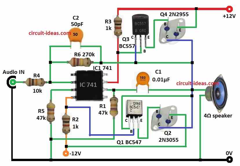
Firstly, circuit uses IC 741 op-amp in inverting mode, then transistor stage increase power to drive speaker.
Also, op-amp controls two transistor pairs like Q1-Q2 and Q3-Q4 and they work like push-pull amp.
Futher, this design give good power and work efficient to drive the speaker.
Audio comes through resistor R4 to pin 3 of non-inverting input of 741 IC and R5 and R6 make voltage divider for op-amp bias.
The op-amp boosts the signal and sends it from pin 6; resistors R1 sets the gain, while capacitor C2 filters high-frequency noise and stabilizes the circuit.
Op-amp output goes to base of Q1 and Q2, Q1 NPN and Q2 NPN handle positive and negative parts of signal.
Lastly, transistors Q3 PNP and Q4 PNP also give more boost to drive 4 ohm speaker and capacitor C1 blocks DC and send only audio to speaker.
Formulas:
Here, are simple formulas for 12W transistor amplifier:
Op-Amp Voltage Gain:
Av = 1 + (R1 / R5)
where,
- R1 is the feedback resistor
- R5 is the input resistor
Power Output:
P = V² / R
where,
- P is the power in watts
- V is the RMS voltage on speaker
- R is the speaker impedance in 4 ohm
How to Build:
To build a 12 Watts Amplifier Circuit using Transistors follow the below mentioned steps for connections:
- First, collect all parts as per circuit diagram.
- Next , pin 2 of IC 741 connect to Audio In through R4 and also to GND.
- Then pin 3 of IC 741 connect to GND through R5.
- After that, pin 4 of IC 741 connect to -12V through R2.
- Then pin 6 connect to speaker through C1 and other side of speaker to GND.
- Next, pin 7 connect to +12V through R3.
- Then Q1 NPN collector join with Q2 NPN collector.
- Also, Q1 base connect between Pin 4 and R2.
- After that, Q1 emitter goes to Q2 base and Q2 emitter goes to -12V.
- Also, Q2 collector also connect to Q4 collector.
- Then R6 connect between R4 and Pin 2 to Q3 collector.
- After that,C2 is in parallel with R6 with same points.
- Next, Q3 collector connect between R6 and Q2 collector.
- Also, Q3 emitter goes to Q4 base.
- Then Q3 base connect between pin 7 and R3.
- After that, Q4 base goes to Q3 emitter, Q4 emitter goes to +12V and collector join with speaker and Q1/Q2 collector.
- Finally, R1 goes between pin 6 and pin 3 and also connects to GND.
Conclusion:
To conclude, this 12 Watts Amplifier Circuit using Transistors is strong and clear for sound, as it uses op-amp and push-pull transistors.
Also, if we make the circuit right, then it gives loud and clean audio, it works well for low ohm speakers and helps upgrade our audio sound system.
How is it a non-inverting amplifier if the input signal is connected to pin 2 of the IC which is the INVERTING INPUT pin? Pin 3 which is the non-inverting pin is connected to GND, which makes it an inverting amplifier. Please clarify if I am missing something.