To begin with, this article for 6V To12V Lead Acid Battery Charger Circuit explains about a dual voltage battery charger circuit.
Lead acid battery needs correct voltage for proper charging, so this charger circuit gives correct charging for both batteries; here, LM317 IC is the main part of the circuit and it gives stable charging voltage.
Furthermore, we can select the battery voltage using a simple switch; also the circuit has a simple and reliable design, making it suitable for DIY electronics projects.
Circuit Working:
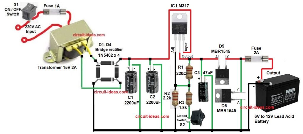
Parts List:
| Components | Values | Quantity |
|---|---|---|
| Resistors | 220Ω, 2.2k, 1.8k | 1 each |
| Capacitors | Electrolytic 2200uF 25V | 2 |
| Electrolytic 47uF 25V | 1 | |
| Semiconductors | IC LM317 | 1 |
| Schottky Diode MBR1545 | 2 | |
| Bridge Diode 1N5402 | 4 | |
| Switch ON / OFF Switch | 1 | |
| ON / OFF Closed Switch | 1 | |
| Fuse1A, 2A Fuse | 2 | |
| Transformer 15V 2A, 220V AC | 1 |
The AC mains supply feeds the transformer, and the transformer reduces the voltage to 15V AC, then the bridge rectifier converts the AC voltage into DC.
After that, capacitors smooth the DC and reduce ripple and then filtered DC goes to LM317 input pin and this LM317 controls charging voltage using resistors.
Now switch selects 6V or 12V mode and then diodes stop reverse current and protect the circuit.
Finally, fuse gives overload protection and then battery starts charging when connected.
How to Build:
To build a 6V To12V Lead Acid Battery Charger Circuit follow the below connection steps:
- First, assemble all parts according to the circuit diagram.
- Next, connect transformer primary to AC mains through switch S1 and fuse F1 and connect transformer secondary 15VAC to bridge rectifier input.
- Now connect bridge rectifier AC terminals to transformer secondary, connect bridge rectifier positive to capacitors and LM317 input and then connect bridge rectifier negative to ground line.
- Also, connect capacitor C1 and C2 positive pins to rectifier positive and connect capacitor negative pins to ground.
- Further, connect LM317 adjust pin to resistors R1, R2 and R3, connect LM317 output pin to diode D5, fuse F2 and battery positive and then connect LM317 input pin to filtered DC from C1 and C2.
- After that, connect diode D5 in series with battery positive and also connect diode D6 across output and ground for protection.
Conclusion:
To conclude, this 6V To12V Lead Acid Battery Charger Circuit is simple and reliable project, as it can charge both 6V and 12V lead acid batteries.
The LM317 provides a stable and safe output voltage, and we can assemble the circuit easily at a low cost; also this circuit is suitable for beginners and DIY electronics projects.
Therefore, remember to use a proper heat sink for the LM317.

Leave a Reply