
When our project needs real power then normal adapter is not enough, sometimes battery drains fast and cheap adapters fail;
Therefore, this 9V 2A to 3A Transistors Based Regulator Circuit is best solution, with strong output, smooth DC and long life performance.
However, battery is not good for high current load, so we used transformer based regulated power supply, as this circuit gives 9V DC output and this output current is around 2A to 3A, as it uses transistor control method.
The circuit uses a 2N3055 as the main power transistor, along with a bridge rectifier and a filter capacitor and the Zener diode provides a reference voltage, which keeps the output voltage stable.
The circuit is simple and its components are easily available, so it is good for lab and hobby use.
Circuit Working:
Parts List:
| Components | Values | Quantity |
|---|---|---|
| Resistors (All resistors are 1/4 watt) | 1.8k, 4.7k, 1.2k | 1 each |
| Capacitors | Electrolytic 4700uF 25V, 470uF 25V | 1 |
| Ceramic 0.47uF | 1 | |
| Power transistors TIP3055, Driver Transistor TIP31, Small signal transistor BC547 | 1 each | |
| Zener Diode 9.1V 1W | 1 | |
| Bridge Diodes 6A4 | 4 | |
| Transformer Primary 110V/220V AC Secondary 0-12V, 2A to 3A | 1 | |
| Fuse 1A | 1 | |
| SPST ON/OFF Switch | 1 | |
| Large heatsink for TIP3055 and small heatsink for TIP31 | 1 |
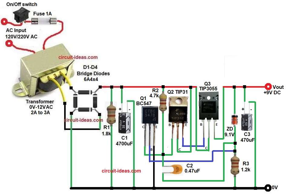
First, AC 220V mains goes to transformer and this transformer rating is 220V to 12V 3A, therefore, voltage steps down from high AC to low AC.
Next, 12V AC goes to bridge rectifier where four 6A4 diodes used, as a result AC converts into pulsating DC.
After that capacitor C1 4700uF filters the DC, therefore, ripple reduces, now we get around 15V to 16V unregulated DC and then this DC goes to regulator section.
Meanwhile, Zener diode ZD1 gives stable reference voltage and at the same time the resistor R3 provides bias current to Zener.
Then, transistor Q1 BC547 works as error amplifier which compares output voltage with Zener reference and if output increases then transistor action changes.
Q2 TIP31 works as driver transistor and thus, it boosts current to drive main transistor.
Finally, Q3 TIP3055 is main pass transistor which handles high current and supplies load and if output voltage increases, conduction reduces, and if output voltage decreases then conduction increases, therefore, output stays near 9V.
Lastly, capacitors C2 and C3 improve stability and also they reduce noise and ripple.
Thus regulated 9V DC output is available at Vout terminal.
How to build:
To build a 9V 2A to 3A Transistors Based Regulator Circuit follow the below connection steps:
- Start, the circuit first by gathering all the circuit components.
- Then, start with transformer primary pins connect to 230V AC through switch and fuse.
- Secondary 12V AC goes to bridge rectifier AC terminals.
- Next, bridge rectifier D1-D4 two AC terminals connect to transformer secondary.
- Positive terminal goes to resistor R1 and filter capacitor positive C1 and negative terminal of C1 goes to ground.
- After that, transistor Q1 BC547 collector pin connect to driver transistor base network.
- Base pin connect to Zener anode and resistor R3 one end and emitter pin goes to ground.
- Now transistor Q2 TIP31 collector pin connect to unregulated DC input supply.
- Base pin connect to Q1 collector and emitter connect to base of Q3 TIP3055.
- Further, transistor Q3 TIP3055 collector pin connect to unregulated DC input.
- Emitter pin goes to Vout output of 9V and base connect to driver transistor emitter Q2.
- Also, Zener Diode connect cathode to output line and anode to one end of capacitor C3.
- Resistor R2 one end connect to unregulated DC input supply and other end goes to base of Q2 and collector of Q1 junction.
- Connect resistor R3 one end between base of Q1 and other end connect to capacitor C2 one end and cathode of Zener diode.
- Lastly, capacitor C3 positive end goes to output and negative end to ground.
Conclusion:
This 9V 2A to 3A Transistors Based Regulator Circuit is simple and is with strong design as it uses transformer, bridge rectifier and transistor regulator which gives stable DC output.
The TIP3055 handles high current easily, but it requires a proper heatsink for effective heat dissipation, also this circuit works well for amplifiers, motor drivers and laboratory testing, and users can easily repair and modify it.
If need higher current then bigger transformer and more cooling required and thus, this circuit is practical and useful for many electronic projects.