This project for Automatic Street Light Circuit using Arduino show street light can think smart.
Light will turn ON when night come and light will turn OFF when sun come; therefore no need of a human to press a switch.
Arduino and LDR do all work automatic and it also save power and make street more smart; simple idea but very useful for city and village both.
Arduino Code:
int sensorPin = A0;
int ledPin = 13;
int sensorValue = 0;

void setup() {
pinMode(ledPin, OUTPUT);
Serial.begin(9600);
}

void loop() {
sensorValue = analogRead(sensorPin);
Serial.println(sensorValue);
if(sensorValue < 500) {
digitalWrite(ledPin, HIGH);
} else {
digitalWrite(ledPin, LOW);
}
delay(100);
}
Coding Explanation:
- A0 pin reads value from LDR sensor.
- If value is less than 500 means dark and LED turns ON.
- If value is more than 500 means light and LED turns OFF.
- Serial monitor shows light level in number.
- Delay gives small pause between readings.
Circuit Working:
Parts List:
| Components | Quantity |
|---|---|
| Resistors 10k and 330Ω | 1 each |
| LDR | 1 |
| Arduino UNO | 1 |
| LED any color | 1 |
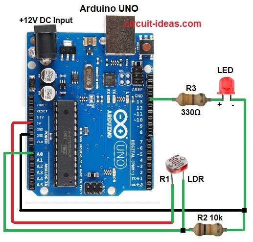
In the above circuit diagram, LDR changes its resistance with light.
In bright light resistance is low and gives high voltage to Arduino and in dark the resistance is high and voltage becomes low.
Then Arduino reads this change and controls LED and LED now has one extra resistor 330Ω and this resistor just controls LED brightness and saves it from damage.
Lastly, when it is night the light glows and when it is day the light goes OFF automatically.
Formula with Calculation:
LDR and resistor make a voltage divider.
Vout = (R2 / (R1 + R2)) × Vin
here,
- R1 is LDR
- R2 is 10k resistor.
This formula gives voltage at A0 pin and for LED we can calculate resistor value using:
R = (Vsource – Vled) / Iled
here,
R = (5 – 2) / 0.01 = 300Ω
So nearest standard resistor used in this circuit is 330Ω.
How to Build:
To build a Automatic Street Light Circuit using Arduino follow the below steps:
- First, gather all the parts as shown in circuit diagram.
- Then LDR one end connect to 5V of Arduino and other end of LDR connect to A0 pin and one side of 10k resistor.
- Also, other side of 10k resistor goes to GND.
- After that, LED positive leg connect to pin 13 through 330Ω resistor and LED negative leg goes to GND.
- Finally, Arduino powered by USB or adapter.
Conclusion:
To conclude, Automatic Street Light Circuit using Arduino saves power, as it works without human help.
Also, it is useful for highways, gardens and streets and then Arduino makes control simple and automatic; furthermore, system works day and night based on light sensor.
Leave a Reply