This Stable 5V 3A Power Source Circuit using IC LM350 is to make stable 5V 3A DC output from AC mains.
It use transformer, bridge rectifier, filter capacitors and LM350 adjustable regulator.
LM350 can give up to 3A current which is good for microcontroller, charger, LED strip and many circuits.
The unregulated power supply works almost the same as earlier article 5V 3A Linear Power Supply Circuit but with little modification.
Circuit Working:
Parts List:
| Components | Value | Quantity |
|---|---|---|
| Resistors | 270Ω , 820Ω, 2.2k | 1 each |
| Capacitors | Electrolytic 2200µF 25V | 3 |
| Ceramic 0.1µF 50V | 2 | |
| Electrolytic 47µF 25V | 1 | |
| Electrolytic 100µF 25V | 1 | |
| Semiconductors | Transformer 12V AC 4A | 1 |
| Bridge Diode 1N5408 | 4 | |
| IC LM350 | 1 | |
| On/Off Switch | 1 | |
| 1A Fuse | 1 | |
| Diodes 1N4007 | 3 |
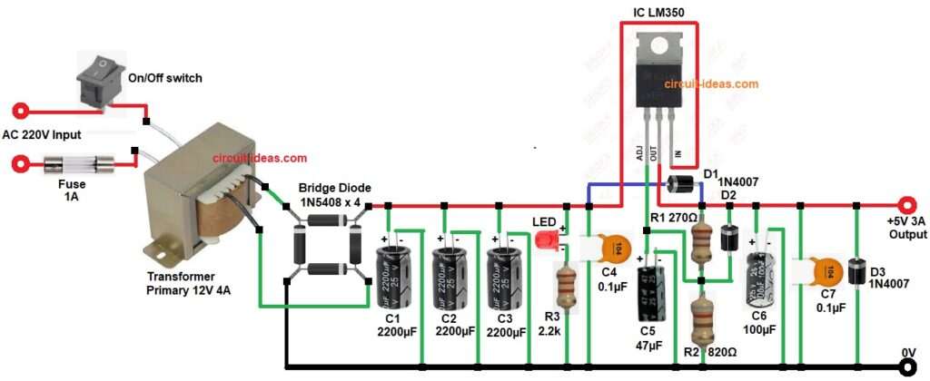
In the above circuit diagram AC 220V goes to switch and fuse.
Transformer is step down AC 220V to AC 12V.
Bridge diode change AC 12V to DC around 16V peak.
Capacitors C1, C2, C3 smooth the DC and reduce the ripple.
LM350 IC take this DC and regulate to stable 5V output.
R1 and R2 resistors make voltage setting network.
D1 protect LM350 from reverse voltage and D2 protect output from reverse current.
Capacitors C4 and C5 keep LM350 stable and C6 and C7 clean final output.
Diodes D3 show polarity protection at output.
Formulas with Calculation:
LM350 output voltage formula:
Vout = 1.25 * (1 + R2 / R1)
where,
- Vout is the voltage that comes out from the regulator IC LM350.
- 1.25 is the reference voltage inside the IC.
- R1 and R2 are two resistors connected to the IC.
- The ratio R2 / R1 controls how high the output voltage becomes.
Now let us calculate:
- R1 is 270 ohm
- R2 is 820 ohm
R2 / R1 = 820 / 270 = 3.037
1 + 3.037 = 4.037
Vout = 1.25 * 4.037
Vout = 5.04V
So output is approx 5V
How to Build:
To build a Stable 5V 3A Power Source Circuit using IC LM350 follow the below steps:
- Assemble all the parts as shown in circuit diagram.
- Transformer AC pin connect to mains and fuse.
- Transformer secondary pin connect to bridge rectifier AC pins.
- Bridge rectifier positive pin connect to filter capacitors C1 positive.
- Bridge negative pin connect to ground line.
- IC LM350 pin In connects to input capacitors.
- LM350 pin out connect to output terminal.
- LM350 Adj pin connect to positive capacitor C5 and negative goes to GND.
- R1 and R2 resistors connect from output pin to Adj pin.
- Connect capacitors C1,C2, C3 and C4 from IC input pin.
- Connect LED and resistor R3 in series from IN pin of IC.
- Capacitor C4 connect between In and ground pin of IC.
- Capacitor C5 connect between Adj and ground.
- Capacitor C6 connect at output to ground.
- Capacitor C7 connect also across output for noise filter.
- Diode D1 connect across Input and Output of LM350 reverse biased.
- Diode D2 connect from output to input reverse protection.
- Diode D3 connect at final output for safety.
Conclusion:
This Stable 5V 3A Power Source Circuit using IC LM350 is simple and strong for give clean 5V 3A.
IC LM350 make stable voltage even if load change.
It needs good heat sink.
Use good transformer and large capacitors for smooth DC.
It is useful for many electronic projects.
Leave a Reply