• Skip to primary navigation
  • Skip to main content
  • Skip to primary sidebar

Circuit Ideas for You

Get free circuit ideas online.

  • Home
  • Privacy Policy
  • About
Home » Simple 5V to 3.3V Converter Circuit using IC LD33V

Simple 5V to 3.3V Converter Circuit using IC LD33V

Last updated on 10 December 2025 by Admin-Lavi Leave a Comment

Here is an article for Simple 5V to 3.3V Converter Circuit using IC LD33V.

This circuit is cheap, works from 5V input and it uses LD33V voltage regulator IC.

We just need to take a phone charger and put a charger output to regulator input.

And then regulator will gives stable 3.3V output which is very easy.

The circuit is good for microcontrollers and sensors.

Circuit Working:

Simple 5V to 3.3V Converter Circuit Diagram using IC LD33V

Parts List:

ComponentValueQuantity
Resistor220Ω1
Capacitors Electrolytic 10uF 25V1
Ceramic 0.1uF1
SemiconductorsVoltage Regulator IC LD33V1
LED any 5mm1

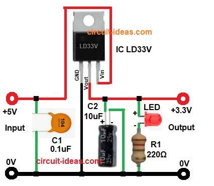
This circuit gives 5V to the LD33V Vin pin and the regulator makes output 3.3V at Vout pin.

Ground pin connect to common ground.

A 0.1uF capacitor is at input side and a 10uF capacitor is at output side.

These capacitors remove noise and they keep voltage stable.

LED with resistor shows power ON and they light only when 3.3V is available.

Resistor limits LED current.

Formulas with Calculation:

LED current formula: I = V / R

    Voltage across resistor = 3.3V – 2.0V for red LED = 1.3V

    If resistor is 220 ohm: I = 1.3 / 220 = 0.0059A approx 6mA

    This is safe current for LED.

    Power dissipation for regulator: P = (Vin – Vout) × Iload

    If input = 5V

    Output = 3.3V

    Load current = 100mA

    P = (5 – 3.3) × 0.1 = 0.17W

    This is low heat and regulator will work fine.

    How to Build:

    To build a Simple 5V to 3.3V Converter Circuit using IC LD33V follow the below connection steps:

    • Gather all the parts as shown in circuit diagram.
    • LD33V Pin 1 is Ground so connect it to GND line.
    • LD33V Pin 2 is Vout connect to 3.3V output line.
    • LD33V Pin 3 is Vin connect to 5V input.
    • Place C1 0.1uF capacitor between Vin and GND.
    • Place C2 10uF capacitor between Vout and GND.
    • Connect LED anode to 3.3V line.
    • Connect R1 resistor from LED cathode to GND.
    • Connect all grounds together.

    Conclusion:

    This Simple 5V to 3.3V Converter Circuit using IC LD33V is very easy.

    It is very cheap and gives stable 3.3V from 5V supply.

    Good for small electronics and is also good for students.

    This circuit is easy to build as it works with very few parts.

    References:

    Datasheet IC LD33V

    Filed Under: Power Supply Circuits

    About Admin-Lavi

    Lavi is a B.Tech electronics engineer with a passion for designing new electronic circuits. Do you have questions regarding the circuit diagrams presented on this blog? Feel free to comment and solve your queries with quick replies

    Previous Post: « Stable 5V 3A Power Source Circuit using IC LM350
    Next Post: 12V 5A Linear Power Supply Circuit »

    Reader Interactions

    Leave a Reply Cancel reply

    Your email address will not be published. Required fields are marked *

    Primary Sidebar


    Categories

    • Alarm Circuits (45)
    • Amplifier Circuits (67)
    • Arduino Projects (99)
    • Audio Circuits (114)
    • Automobile Circuits (19)
    • Battery Charger Circuits (65)
    • Free Energy (13)
    • Heater and Temperature Controllers (13)
    • High Voltage (1)
    • Indicator Circuits (45)
    • Inverter Circuits (20)
    • IoT projects (1)
    • LDR Circuits (26)
    • LED and Lamps (148)
    • Meters and Testers (30)
    • Motor Controllers (22)
    • Oscillator Circuits (39)
    • Power Supply Circuits (104)
    • Remote Control Circuits (10)
    • Security and Protection (29)
    • Sensors and Detectors (126)
    • Solar Circuits (29)
    • Timer Circuits (41)
    • Transistor Circuits (87)
    • Transmitter Circuit (17)
    • Tutorials (8)
    • Water Level Controller (6)

    Recent Posts

    • 12V Battery Low Voltage Alarm Circuit
    • Low Voltage Alert Circuit for 9V Battery
    • Digital Code Lock Circuit using IC 4017
    • Darkness Activated LED Circuit
    • Fan Start 10 Second Delay Timer Circuit

    Recent Comments

    1. TDHofstetter on DIY Variable Power Supply Circuit using Arduino
    2. feathbuff on Simple Micro Ampere Meter Circuit
    3. Admin-Lavi on Simple School Project Multimeter Circuit
    4. choke on Simple School Project Multimeter Circuit
    5. Admin-Lavi on Analog to Digital Converter Circuit using IC 555

    Copyright © 2026 | New Circuit Ideas