This is a simple and easy to make 12V 5A Linear Power Supply Circuit, as it uses transformer, bridge rectifier, filter capacitor, control transistor and regulator IC.
Circuit gives clean 12V output and it is good for LED strips, small radios, car stereo tests, chargers and hobby projects; also the circuit is easy to build and its parts are common.
Circuit Working:
Parts List:
| Components | Values | Quantity |
|---|---|---|
| Resistors | 50Ω, 0.12Ω 5W | 1 each |
| Capacitors | Electrolytic 4700uF 50V, 470uF 25V | 1 each |
| Semiconductors | IC 7812 voltage regulator | 1 |
| Power Transistor 2N3792 | 1 | |
| Driver Transistor 2N6049 | 1 | |
| Diodes Bridge rectifier 6A10 | 4 | |
| Transformer 220V AC ,12V 4A output | 1 | |
| Fuse 1A or 2A | 1 | |
| On/Off switch | 1 | |
| Load 12V up to 5A | 1 |
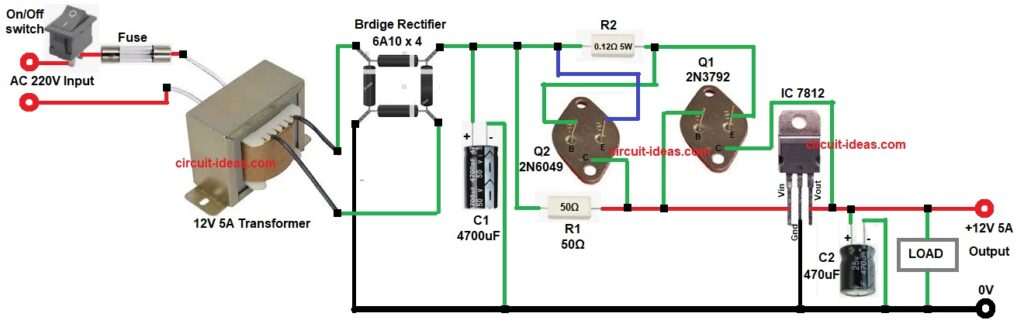
AC mains goes to transformer and the transformer steps down AC to around 15V, then bridge rectifier converts AC to DC and big capacitor C1 smooth the ripple.
After that, transistor Q1 and Q2 work like pass transistor and driver transistor and then transistor Q1 gives current boost up to 5A.
Now IC 7812 hold voltage at 12V stable and then R1 and R2 help current sharing and drive; also output capacitor C2 keep output stable.
Finally, fuse and switch protect the circuit and load takes the output current from the power supply.
How to Build:
To build a 12V 5A Linear Power Supply Circuit follow the below connection steps:
- First, take all parts same like circuit diagram.
- Next, transformer primary wires go to AC mains by switch and fuse and transformer secondary wires go to bridge rectifier AC pins.
- Then bridge rectifier plus pin go to big capacitor positive and bridge rectifier minus pin go to ground.
- After that, Q2 2N6049 base connect to Q1 emitter and resistor R2, Q2 collector go to Q1 base and also go to IC input pin and Q2 emitter connect to resistor R1 and R2 joint point.
- Now Q1 2N3792 base connect to IC input pin, Q1 emitter go to Q2 base and then Q1 collector connect between IC output pin and capacitor C2.
- Further, connect IC 7812 pin 1 input to the Q1 base side, connect pin 2 ground to the circuit ground, and connect pin 3 output to the load positive terminal.
- Lastly, output capacitor C2 connect between IC output and ground and then all ground points join together in whole circuit.
Conclusion:
To conclude, this 12V 5A Linear Power Supply Circuit gives strong and stable 12V at 5A, also its parts are cheap and easy and need big heat sink because power loss is high.
Circuit is good for learning linear supply working and is also easy for hobby builders and repair work.

Leave a Reply