• Skip to primary navigation
  • Skip to main content
  • Skip to primary sidebar

Circuit Ideas for You

Get free circuit ideas online.

  • Home
  • Privacy Policy
  • About
Home » Transformer Based 12V DC 3A Power Supply Circuit

Transformer Based 12V DC 3A Power Supply Circuit

Last updated on 22 December 2025 by Admin-Lavi Leave a Comment

Need a strong 12V DC supply for our electronics projects?

A stable and powerful DC supply is the heart of any electronics project.

This Transformer Based 12V DC 3A Power Supply Circuit delivers clean and reliable power.

It converts AC mains into smooth DC power and it provides high current with low noise output.

It is simple to build and uses easily available components.

Perfect for hobbyists, students and DIY electronics lovers.

Circuit Working:

Transformer Based 12V DC 3A Power Supply Circuit Diagram

Parts List:

Components NameSpecificationQuantity
Resistor1.2k 1/4 watt1
CapacitorsElectrolytic 2200uF 25V4
Ceramic 0.1uF1
Bridge Rectifier 6A 100V1
LED any 5mm1
Step-Down Transformer 12V, 3A Secondary, 220V AC Primary1
ON/OFF Switch SPST1
Fuse 1A1

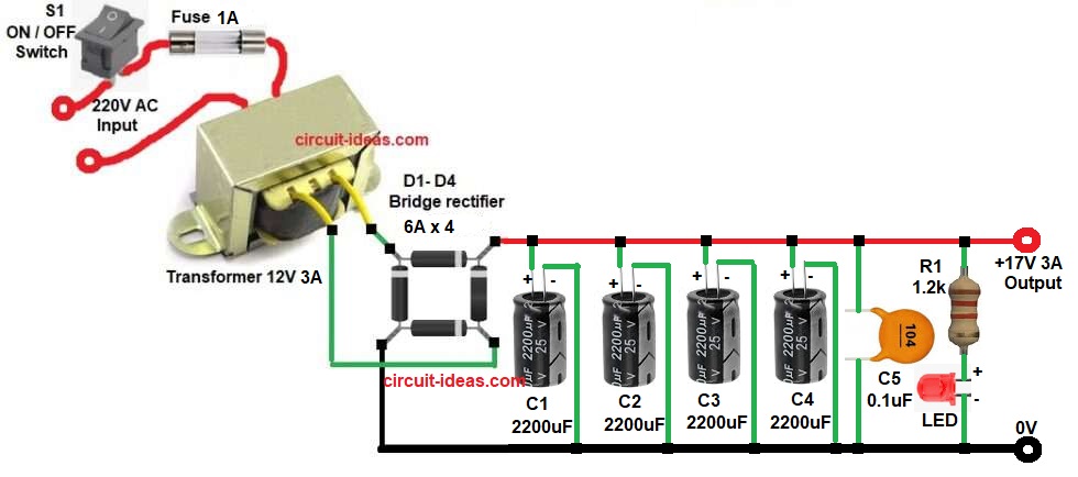
In this article transformer reduces high AC voltage to 12V AC.

Bridge rectifier changes AC into pulsating DC.

Capacitors C1 to C4 make the DC more smooth and capacitor C5 removes small high frequency noise.

LED turns ON when DC power is available and DC output is taken from capacitor positive and ground terminals.

How to Build:

To build a Transformer Based 12V DC 3A Power Supply Circuit following are the steps we need to follow:

  • Gather all the parts as shown in circuit diagram.
  • Transformer primary pins connect to AC mains via switch and fuse.
  • Transformer secondary pins connect to bridge rectifier AC pins.
  • Bridge rectifier positive pin connects to capacitor positive rails.
  • Bridge rectifier negative pin connects to ground line.
  • All capacitor positive pins connect together at the output.
  • All capacitor negative pins connect to ground.
  • LED anode connects to output through resistor R1.
  • LED cathode connects to ground.

Conclusion:

This Transformer Based 12V DC 3A Power Supply Circuit is simple and effective.

It uses easily available components and provides high current DC output.

It is best for non-sensitive electronics and by adding a regulator we can improve voltage stability.

References:

What is the circuit diagram of a 12V DC power supply and explain its functions?

Filed Under: Power Supply Circuits

About Admin-Lavi

Lavi is a B.Tech electronics engineer with a passion for designing new electronic circuits. Do you have questions regarding the circuit diagrams presented on this blog? Feel free to comment and solve your queries with quick replies

Previous Post: « Regulated 9V Power Supply Circuit using IC 7809
Next Post: 6V To12V Lead Acid Battery Charger Circuit »

Reader Interactions

Leave a Reply Cancel reply

Your email address will not be published. Required fields are marked *

Primary Sidebar


Categories

  • Alarm Circuits (45)
  • Amplifier Circuits (67)
  • Arduino Projects (99)
  • Audio Circuits (114)
  • Automobile Circuits (19)
  • Battery Charger Circuits (65)
  • Free Energy (13)
  • Heater and Temperature Controllers (13)
  • High Voltage (1)
  • Indicator Circuits (45)
  • Inverter Circuits (20)
  • IoT projects (1)
  • LDR Circuits (26)
  • LED and Lamps (148)
  • Meters and Testers (30)
  • Motor Controllers (22)
  • Oscillator Circuits (39)
  • Power Supply Circuits (104)
  • Remote Control Circuits (10)
  • Security and Protection (29)
  • Sensors and Detectors (126)
  • Solar Circuits (29)
  • Timer Circuits (41)
  • Transistor Circuits (87)
  • Transmitter Circuit (17)
  • Tutorials (8)
  • Water Level Controller (6)

Recent Posts

  • 12V Battery Low Voltage Alarm Circuit
  • Low Voltage Alert Circuit for 9V Battery
  • Digital Code Lock Circuit using IC 4017
  • Darkness Activated LED Circuit
  • Fan Start 10 Second Delay Timer Circuit

Recent Comments

  1. TDHofstetter on DIY Variable Power Supply Circuit using Arduino
  2. feathbuff on Simple Micro Ampere Meter Circuit
  3. Admin-Lavi on Simple School Project Multimeter Circuit
  4. choke on Simple School Project Multimeter Circuit
  5. Admin-Lavi on Analog to Digital Converter Circuit using IC 555

Copyright © 2026 | New Circuit Ideas