In todays world power supply plays a very important role, because most electronics need stable 5V DC; but sometimes if the input voltage is high like for example 12V battery or adapter, then we must reduce voltage safely.
Therefore, this buck converter reduces the voltage with high efficiency and this 12V to 5V Buck Converter Circuit uses only transistors instead of an IC, making the circuit low cost, simple and easy to understand.
Also, this circuit gives about 1A current and thus it is good for small projects.
Circuit Working:
Parts List:
| Components | Values | Quantity |
|---|---|---|
| Resistors | 2.2k, 470Ω | 1 each |
| 220Ω | 2 | |
| Capacitors | Electrolytic 1000uF 25V | 2 |
| Power Transistor TIP42 | 1 | |
| Transistor 2N2222 | 2 | |
| Schottky Diode 1N5819 | 1 | |
| Coil Inductor 220uH | 1 | |
| Zener Diode 5.1V | 1 | |
| Input Power Supply 12V DC 0.5A | 1 | |
| Output Power 5V DC 1A | 1 | |
| Heat sink for TIP42 | 1 |
The above circuit converts 12V DC to 5V DC as it works on switching principle and therefore, power loss is less.
First, the circuit receives a 12 V DC input and then capacitor C1 filters the input voltage by removing noise and reducing ripple.
TIP42 acts as the main switch and it turns ON and OFF at a very high speed, while transistors Q2 and Q3 control its switching.
When TIP42 turns ON, current starts flowing through inductor L1, storing energy in it and a the same time, diode D1 becomes reverse-biased, so it does not conduct.
Next, when TIP42 becomes OFF the inductor releases stored energy and then current flows through diode D1 and so output voltage maintained.
Meanwhile, capacitor C2 filters output and ripple becomes very low and output becomes smooth DC.
Then Zener diode checks output voltage, when voltage reaches 5.1V and Zener starts conducting little.
Therefore, because of this Q3 turns ON and then Q2 also, turns ON and so base current of TIP42 reduces and finally, switching action becomes less, with output voltage stays stable and so feedback loop works correctly.
How to Build:
To build a 12V to 5V Buck Converter Circuit using Transistors follow the below connection steps:
- Start, the circuit first by collecting all the components as shown in circuit diagram.
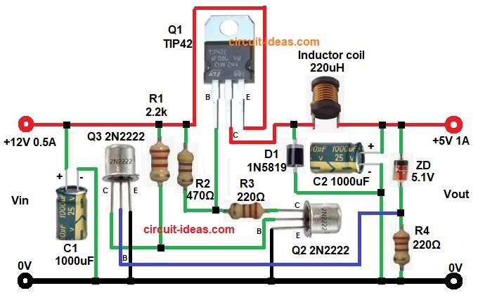
- Then start with Q1 TIP42 transistor emitter pin connects to input 12V, collector connects to the junction of diode D1 and inductor L1 and base connects to R2 and R3 junction
- Next, start with Q2 2N2222 transistor emitter connects to ground, base connects to collector of transistor Q3 and collector connects to base of Q1 through resistor R3.
- Q3 2N2222 transistor emitter connects to ground, base connects between Zener diode and R4 and collector connects to Q2 base and resistor R1.
- Capacitor C1 connects across input supply.
- Inductor L1 one end connects to Q1 TIP42 collector and cathode of diode D1 and other end connects to 5V output.
- Also, positive of capacitor C2 and cathode of ZD1 connect to output 5V.
- Lastly, anode connects to base of Q3 and resistor R4 one end and other end of R4 connects to GND.
Conclusion:
To conclude, this 12V to 5V Buck Converter Circuit using Transistors is simple project to build, as it uses only basic components and so beginners can understand easily.
Moreover, it saves power, heat loss is low and thus it is better than 7805 regulator IC.
Hence, this circuit is good and is best for learning switching supplies and also is useful in DIY electronics projects.
Leave a Reply